Diese Version enthält möglicherweise inkorrekte Änderungen. Wechsle zur letzten geprüften Version.
Was du brauchst
-
Dieser Schritt ist noch nicht übersetzt. Hilf mit, ihn zu übersetzen!
-
Place the TV face down on a flat smooth surface as to not scratch the screen.
-
Using a Phillips #2 screwdriver remove the four 8mm screws attaching the stand to the TV.
-
-
Dieser Schritt ist noch nicht übersetzt. Hilf mit, ihn zu übersetzen!
-
Lift the stand off the television.
-
-
Dieser Schritt ist noch nicht übersetzt. Hilf mit, ihn zu übersetzen!
-
Remove the two back panels by prying them out with your hands.
-
-
Dieser Schritt ist noch nicht übersetzt. Hilf mit, ihn zu übersetzen!
-
Using a Phillips #2 screwdriver, remove the eight 6mm Phillips screws located around the edge.
-
Using a Phillips #2 screwdriver, remove the two 6mm Phillips screws located near the inputs.
-
-
-
Dieser Schritt ist noch nicht übersetzt. Hilf mit, ihn zu übersetzen!
-
Using your hands, gently lift and remove the back case of the television.
-
-
Dieser Schritt ist noch nicht übersetzt. Hilf mit, ihn zu übersetzen!
-
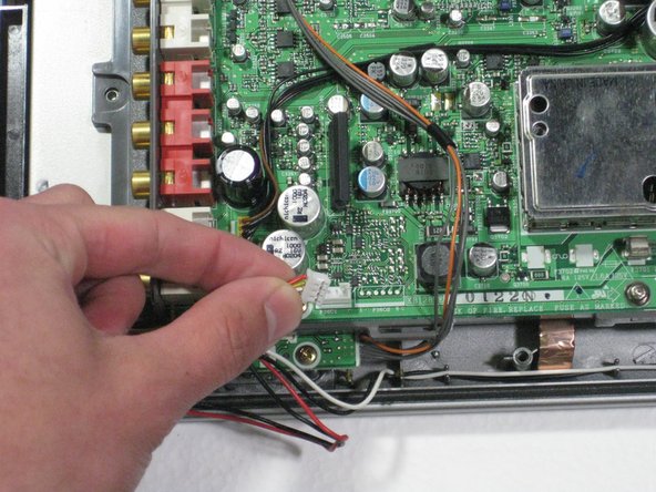
Remove the two speaker cables and the connector from the circuit board by pinching the plastic connectors and firmly pulling up.
-
-
Dieser Schritt ist noch nicht übersetzt. Hilf mit, ihn zu übersetzen!
-
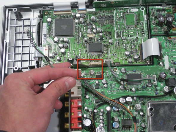
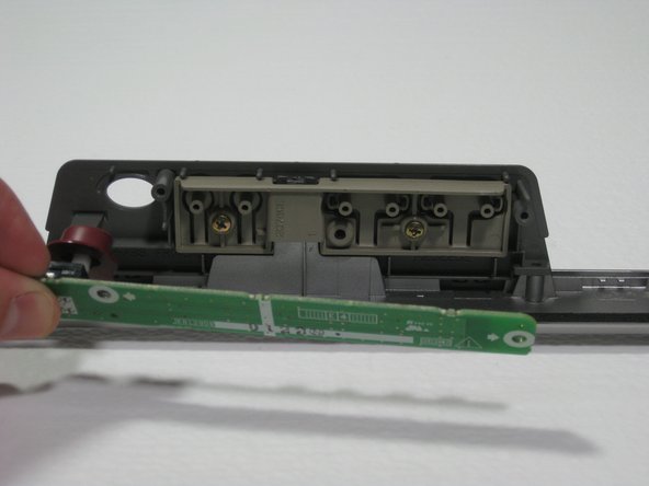
Remove the green and gray power connector from the side of the buttons panel at the top of the television.
-
Remove the green/gray to orange/gray connector from the center of the circuit board.
-
-
Dieser Schritt ist noch nicht übersetzt. Hilf mit, ihn zu übersetzen!
-
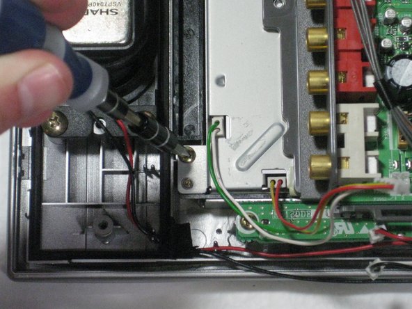
Remove the four 5mm phillips screws attaching the LCD and circuit board to the front case.
-
-
Dieser Schritt ist noch nicht übersetzt. Hilf mit, ihn zu übersetzen!
-
Lift the circuit board/LCD block from the case by lifting the near side of the circuit board and sliding it under the button frame.
-
-
Dieser Schritt ist noch nicht übersetzt. Hilf mit, ihn zu übersetzen!
-
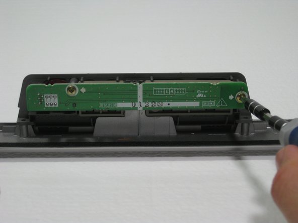
Remove the two 6mm Phillips screws.
-
Pull the board toward you, giving you access to the power button.
-


Team

Cal Poly, Team 1-11, Amido Winter 2011 Mitglied von Cal Poly, Team 1-11, Amido Winter 2011
CPSU-AMIDO-W11S1G11
4 Mitglieder
9 Anleitungen geschrieben