Diese Version enthält möglicherweise inkorrekte Änderungen. Wechsle zur letzten geprüften Version.
Was du brauchst
-
Dieser Schritt ist noch nicht übersetzt. Hilf mit, ihn zu übersetzen!
-
Slide the battery latch down the side of the camera with your hands.
-
The latch will automatically pop open.
-
-
Dieser Schritt ist noch nicht übersetzt. Hilf mit, ihn zu übersetzen!
-
Unlatch the clip over the battery.
-
The battery will partially pop out.
-
-
Dieser Schritt ist noch nicht übersetzt. Hilf mit, ihn zu übersetzen!
-
Remove the battery from the camera.
-
-
Dieser Schritt ist noch nicht übersetzt. Hilf mit, ihn zu übersetzen!
-
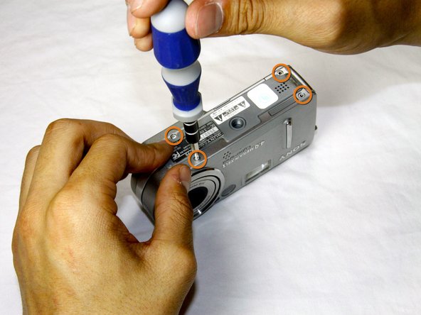
Remove the four 3.0mm Phillips #000 screws on the top of the camera with the phillips screwdriver.
-
Remove the additional four 3.0mm Phillips #000 screws on the bottom of the camera.
-
-
Dieser Schritt ist noch nicht übersetzt. Hilf mit, ihn zu übersetzen!
-
Once the screws are removed, slowly remove the back casing from the rest of the camera.
-
-
Dieser Schritt ist noch nicht übersetzt. Hilf mit, ihn zu übersetzen!
-
Then, pull the front case away from the rest of the camera.
-
-
Dieser Schritt ist noch nicht übersetzt. Hilf mit, ihn zu übersetzen!
-
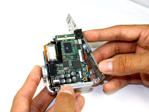
After the casing is removed, the camera should look as shown.
-
-
Dieser Schritt ist noch nicht übersetzt. Hilf mit, ihn zu übersetzen!
-
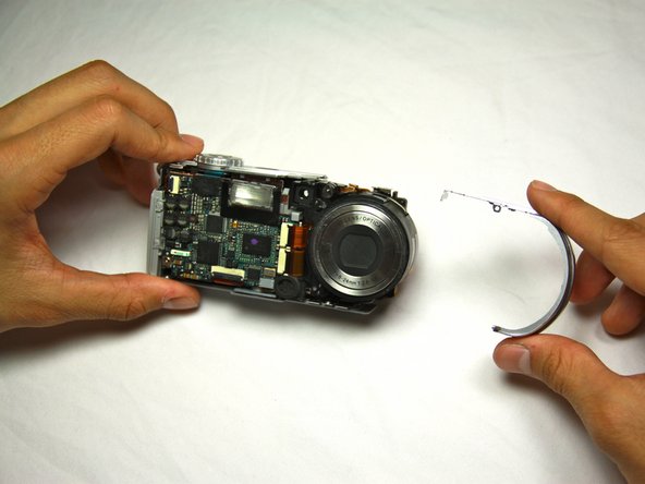
Dislodge the round casing from the lens.
-
Pull it away from the rest of the camera.
-
-
-
Dieser Schritt ist noch nicht übersetzt. Hilf mit, ihn zu übersetzen!
-
Unscrew the two 4.0mm Phillips #000 screws from the display.
-
-
Dieser Schritt ist noch nicht übersetzt. Hilf mit, ihn zu übersetzen!
-
Pull the two ribbon cables out of their slots on the back circuit board.
-
-
Dieser Schritt ist noch nicht übersetzt. Hilf mit, ihn zu übersetzen!
-
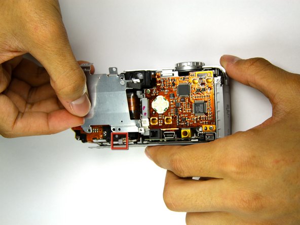
Remove the three 4.0mm Phillips #000 screws holding the back panel in place.
-
-
Dieser Schritt ist noch nicht übersetzt. Hilf mit, ihn zu übersetzen!
-
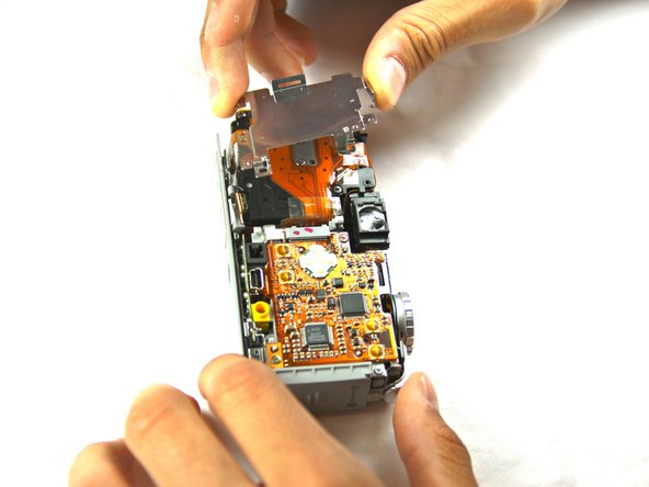
Work the back panel out from under the small grey clip.
-
Slide the back panel off of the camera by dislodging it from the remaining clips.
-
Below is a flat, orange cable connecting the lens to the motherboard.
-
-
Dieser Schritt ist noch nicht übersetzt. Hilf mit, ihn zu übersetzen!
-
Turn the camera over so that you can see the front of the lens.
-
Two connectors link the lens to the motherboard.
-
Gently bring the lens away from the camera.
-
-
Dieser Schritt ist noch nicht übersetzt. Hilf mit, ihn zu übersetzen!
-
Using the flat end of the plastic spudger tool, flip up the black tabs on the connectors.
-
-
Dieser Schritt ist noch nicht übersetzt. Hilf mit, ihn zu übersetzen!
-
Gently pull out the cables and move the lens away from the rest of the camera.
-
You should now have two distinct, separate components.
-
-
Dieser Schritt ist noch nicht übersetzt. Hilf mit, ihn zu übersetzen!
-
Rotate the bottom panel upwards and pull away with your hand.
-
-
Dieser Schritt ist noch nicht übersetzt. Hilf mit, ihn zu übersetzen!
-
Remove the one 2.5mm Phillips #000 screw on the bottom corner of the motherboard.
-
-
Dieser Schritt ist noch nicht übersetzt. Hilf mit, ihn zu übersetzen!
-
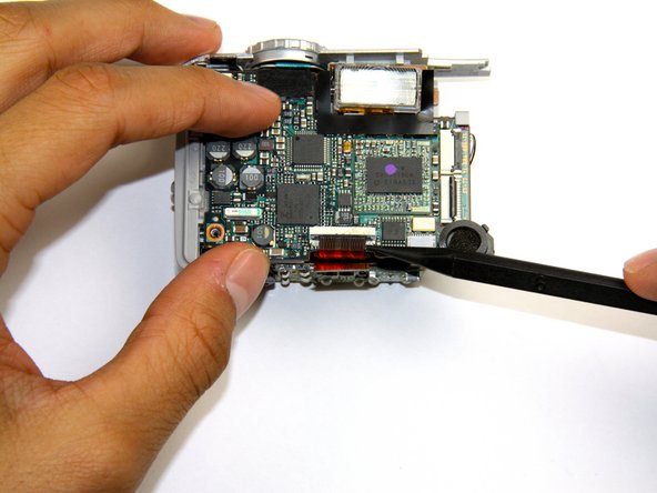
Lift the black tab holding the top-left ribbon cable in place with the spudger tool.
-
Remove the ribbon cable with the spudger by carefully pulling the cable directly out of the slot.
-
-
Dieser Schritt ist noch nicht übersetzt. Hilf mit, ihn zu übersetzen!
-
Lift the black tab that locks the orange ribbon cable in place.
-
Remove the ribbon cable by gently pulling it out of the slot with the spudger.
-
-
Dieser Schritt ist noch nicht übersetzt. Hilf mit, ihn zu übersetzen!
-
Remove the second ribbon cable below the first one by gently pulling it out of the slot with the spudger.
-
-
Dieser Schritt ist noch nicht übersetzt. Hilf mit, ihn zu übersetzen!
-
Remove the ribbon cable to the right of the bottom two ribbon cables with the spudger.
-
-
Dieser Schritt ist noch nicht übersetzt. Hilf mit, ihn zu übersetzen!
-
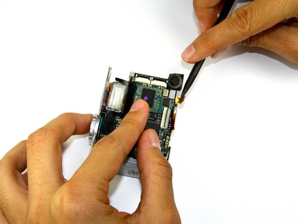
Pull the motherboard out of the slot on the side of the camera where the lens used to be attached.
-
-
Dieser Schritt ist noch nicht übersetzt. Hilf mit, ihn zu übersetzen!
-
Lift the motherboard away from the camera.
-
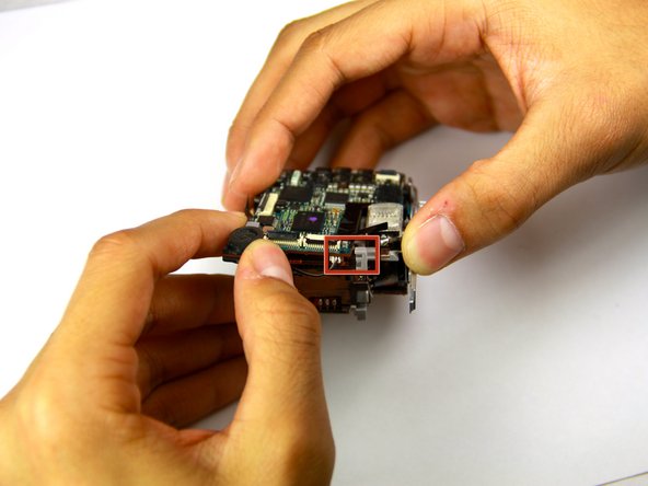
Detach the final ribbon cable connecting the motherboard to the rest of the camera.
-
-
Dieser Schritt ist noch nicht übersetzt. Hilf mit, ihn zu übersetzen!
-
The motherboard should now be fully disconnected from the rest of the camera.
-


Team

Cal Poly, Team 17-25, Amido Spring 2012 Mitglied von Cal Poly, Team 17-25, Amido Spring 2012
CPSU-AMIDO-S12S17G25
4 Mitglieder
14 Anleitungen geschrieben