Diese Version enthält möglicherweise inkorrekte Änderungen. Wechsle zur letzten geprüften Version.
Was du brauchst
-
Dieser Schritt ist noch nicht übersetzt. Hilf mit, ihn zu übersetzen!
-
Flip the laptop over so the Vaio logo is facing down.
-
Locate the battery at the top and Find the release and unlock slides on the battery.
-
Slide the unlock tab to the unlock position.
-
Slide the release tab in the direction of the arrow, i.e. towards the unlock tab.
-
-
Dieser Schritt ist noch nicht übersetzt. Hilf mit, ihn zu übersetzen!
-
With the tabs still in the unlock position, slide the battery away from the main case.
-
-
Dieser Schritt ist noch nicht übersetzt. Hilf mit, ihn zu übersetzen!
-
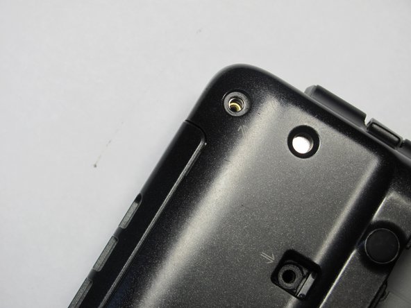
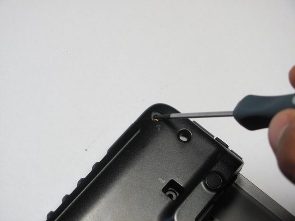
Flip the computer over so the Vaio logo is facedown.
-
Unscrew the 2 screws next to the battery.
-
-
Dieser Schritt ist noch nicht übersetzt. Hilf mit, ihn zu übersetzen!
-
Flip the computer over again so the Vaio logo is face up.
-
Open the lid.
-
-
Dieser Schritt ist noch nicht übersetzt. Hilf mit, ihn zu übersetzen!
-
Press down on the outer gray shell around the keyboard.
-
Use the spudger to gently lift keyboard.
-
-
Dieser Schritt ist noch nicht übersetzt. Hilf mit, ihn zu übersetzen!
-
Lift up lever underneath the ribbon to detach the keyboard.
-
-
Dieser Schritt ist noch nicht übersetzt. Hilf mit, ihn zu übersetzen!
-
Remove memory/wireless compartment cover.
-
-
-
Dieser Schritt ist noch nicht übersetzt. Hilf mit, ihn zu übersetzen!
-
Flip so the Vaio Logo is face down.
-
Locate and remove a total of 8 screws on the bottom.
-
-
Dieser Schritt ist noch nicht übersetzt. Hilf mit, ihn zu übersetzen!
-
Find and remove 5 screws (they all have arrows next to them) from cover.
-
-
Dieser Schritt ist noch nicht übersetzt. Hilf mit, ihn zu übersetzen!
-
Flip the laptop over so the Vaio logo is face up.
-
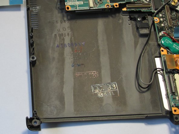
Use the spudger to pop up the upper casing.
-
Remove the wires that are attaching the upper casing to the motherboard.
-
-
Dieser Schritt ist noch nicht übersetzt. Hilf mit, ihn zu übersetzen!
-
Remove the screw holding the optical drive casing to the logic board.
-
-
Dieser Schritt ist noch nicht übersetzt. Hilf mit, ihn zu übersetzen!
-
Locate ribbon connecting optical drive case to logic board.
-
Pop off the ribbon.
-
Remove the metal PC-Card cage.
-
-
Dieser Schritt ist noch nicht übersetzt. Hilf mit, ihn zu übersetzen!
-
Remove the four screws holding the optical drive to the logic board.
-
-
Dieser Schritt ist noch nicht übersetzt. Hilf mit, ihn zu übersetzen!
-
Locate brown locking tab above optical drive.
-
Lift up on brown locking tab until ribbon is loose.
-
Gently slide out and remove the optical drive from the computer.
-
-
Dieser Schritt ist noch nicht übersetzt. Hilf mit, ihn zu übersetzen!
-
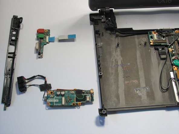
Remove the blue ribbon from the Ethernet Circuit Board.
-
-
Dieser Schritt ist noch nicht übersetzt. Hilf mit, ihn zu übersetzen!
-
Remove the screws near the Ethernet Port circuit board.
-
-
Dieser Schritt ist noch nicht übersetzt. Hilf mit, ihn zu übersetzen!
-
Remove the screws for the second ethernet circuit board.
-


Rückgängig: Ich habe diese Anleitung nicht absolviert.
Ein:e weitere:r Nutzer:in hat diese Anleitung absolviert.

Team

Cal Poly, Team 16-4, Maness Spring 2010 Mitglied von Cal Poly, Team 16-4, Maness Spring 2010
CPSU-MANESS-S10S16G4
4 Mitglieder
30 Anleitungen geschrieben