Diese Version enthält möglicherweise inkorrekte Änderungen. Wechsle zur letzten geprüften Version.
Was du brauchst
-
Dieser Schritt ist noch nicht übersetzt. Hilf mit, ihn zu übersetzen!
-
Remove the two black 6.4mm Phillips screws from the back of the device.
-
-
Dieser Schritt ist noch nicht übersetzt. Hilf mit, ihn zu übersetzen!
-
Using a plastic opening tool, work your way around the edges of the device, carefully prying off the front panel.
-
-
Dieser Schritt ist noch nicht übersetzt. Hilf mit, ihn zu übersetzen!
-
Remove the two 2.8 mm phillips screws located on either side of the device near the top.
-
-
Dieser Schritt ist noch nicht übersetzt. Hilf mit, ihn zu übersetzen!
-
Carefully pull the top piece away from the device.
-
-
Dieser Schritt ist noch nicht übersetzt. Hilf mit, ihn zu übersetzen!
-
Remove the two 2.8mm silver Phillips screws on the sides of the frame.
-
Insert a plastic prying tool between the bottom of the case and the motherboard.
-
Pry up the assembly and lift it away from the case.
-
-
-
Dieser Schritt ist noch nicht übersetzt. Hilf mit, ihn zu übersetzen!
-
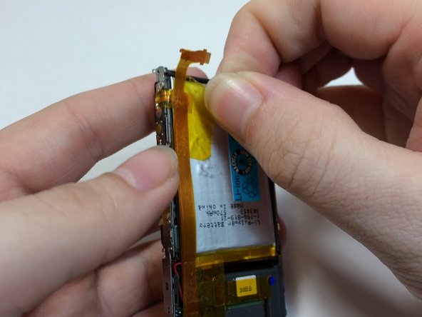
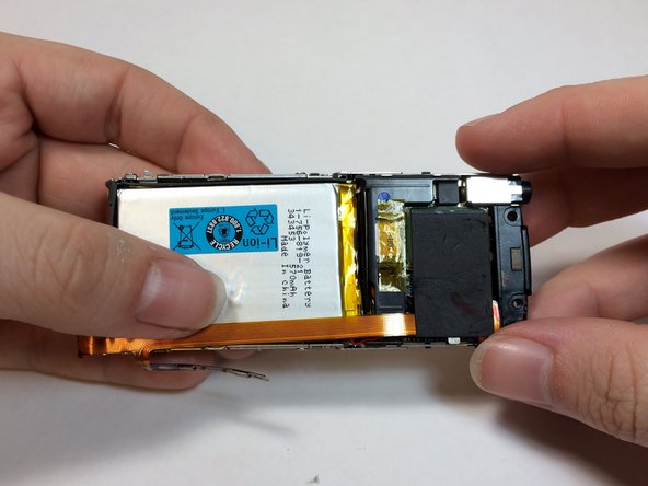
Remove the yellow tape from the battery and volume control module.
-
-
Dieser Schritt ist noch nicht übersetzt. Hilf mit, ihn zu übersetzen!
-
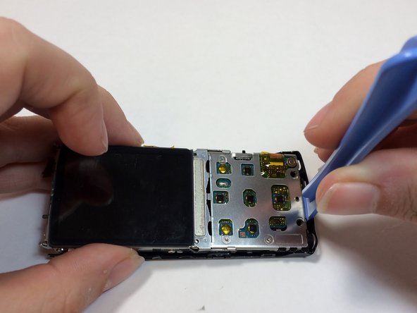
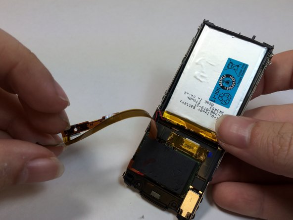
Use a prying tool to pry under the volume control module.
-
-
Dieser Schritt ist noch nicht übersetzt. Hilf mit, ihn zu übersetzen!
-
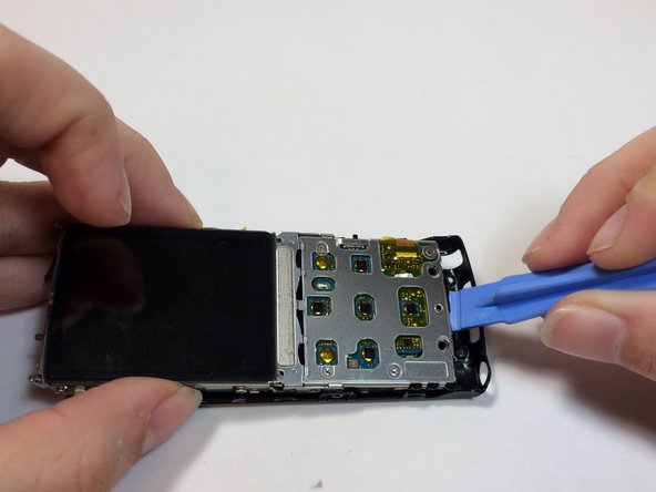
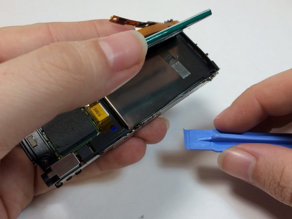
Remove the tape from EMF shield and the LCD housing.
-
Lift up on the volume control ribbon.
-
-
Dieser Schritt ist noch nicht übersetzt. Hilf mit, ihn zu übersetzen!
-
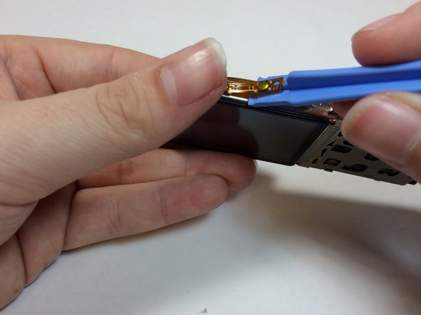
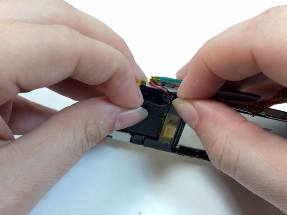
Insert a plastic opening tool under the battery and lift up to remove it.
-
-
Dieser Schritt ist noch nicht übersetzt. Hilf mit, ihn zu übersetzen!
-
Remove the black shielding tape from above the Hard Drive.
-
Peel the foam cover away from the hard drive.
-
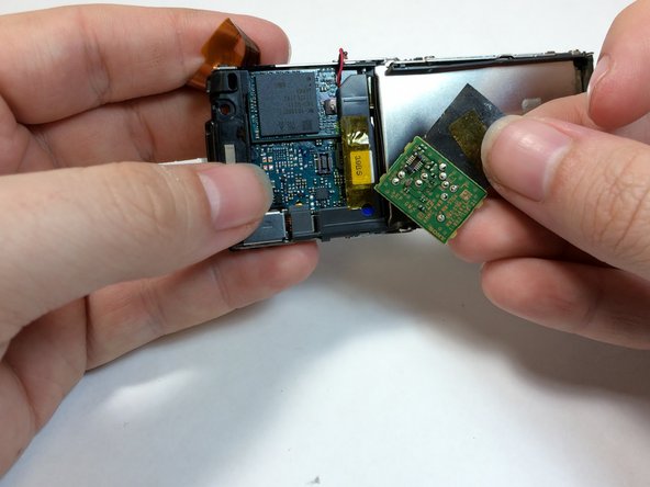
Use a plastic opening tool to remove the EMF chip from the motherboard.
-
-
Dieser Schritt ist noch nicht übersetzt. Hilf mit, ihn zu übersetzen!
-
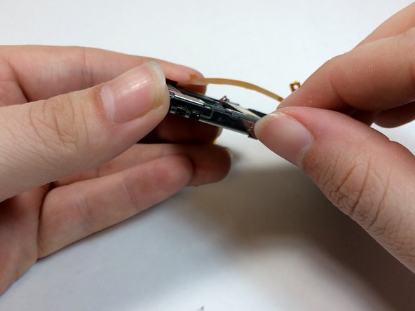
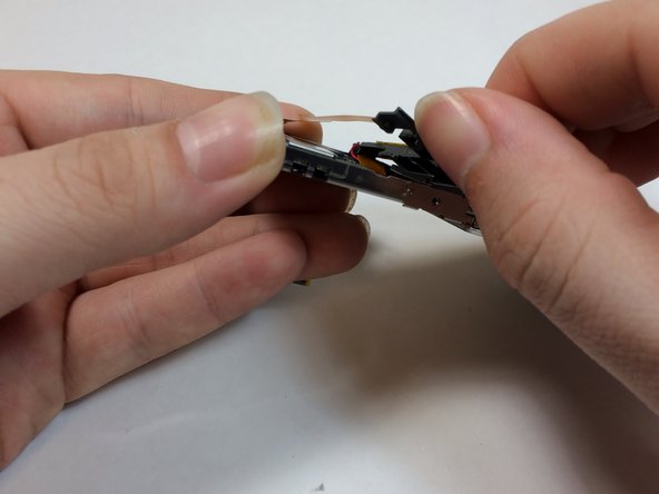
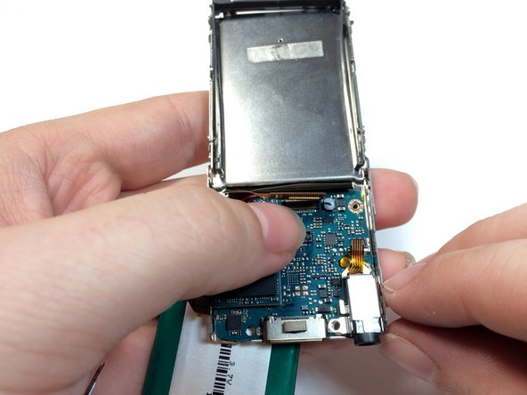
Remove the plastic bracket by pushing up with your thumb to expose the display connection.
-
-
Dieser Schritt ist noch nicht übersetzt. Hilf mit, ihn zu übersetzen!
-
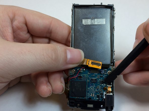
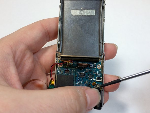
Use the flat end of a spudger to flip up the retaining flap on the audio jack module.
-
-
Dieser Schritt ist noch nicht übersetzt. Hilf mit, ihn zu übersetzen!
-
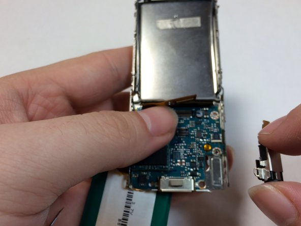
Peel back the ribbon for the audio jack and remove the 1.8mm silver Phillips screw.
-
-
Dieser Schritt ist noch nicht übersetzt. Hilf mit, ihn zu übersetzen!
-
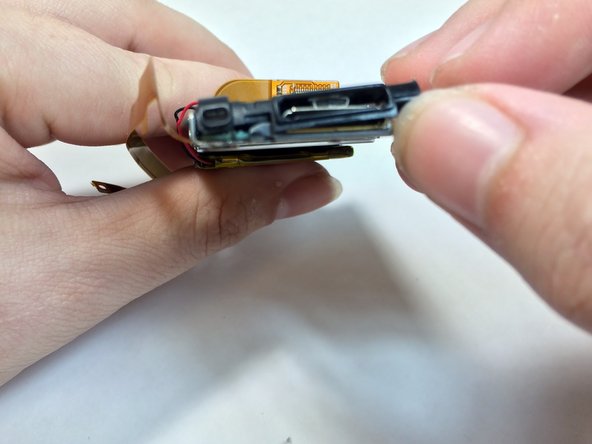
Remove the mic casing by pushing up and in.
-
Remove the headphone jack and the bottom casing.
-


Rückgängig: Ich habe diese Anleitung nicht absolviert.
2 weitere Nutzer:innen haben diese Anleitung absolviert.
Team

USF Tampa, Team 4-2, Brown Winter 2015 Mitglied von USF Tampa, Team 4-2, Brown Winter 2015
USFT-BROWN-W15S4G2
4 Mitglieder
6 Anleitungen geschrieben