Diese Version enthält möglicherweise inkorrekte Änderungen. Wechsle zur letzten geprüften Version.
Was du brauchst
-
Dieser Schritt ist noch nicht übersetzt. Hilf mit, ihn zu übersetzen!
-
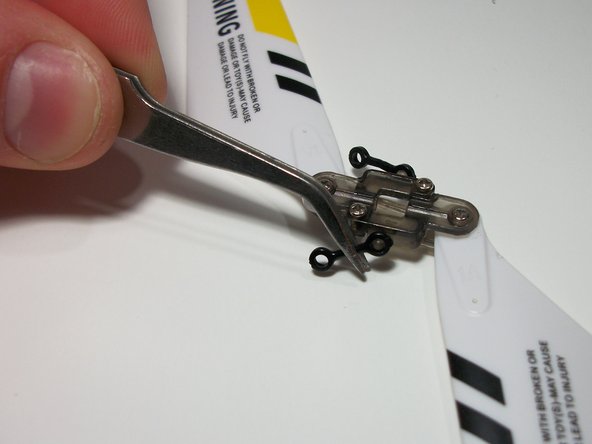
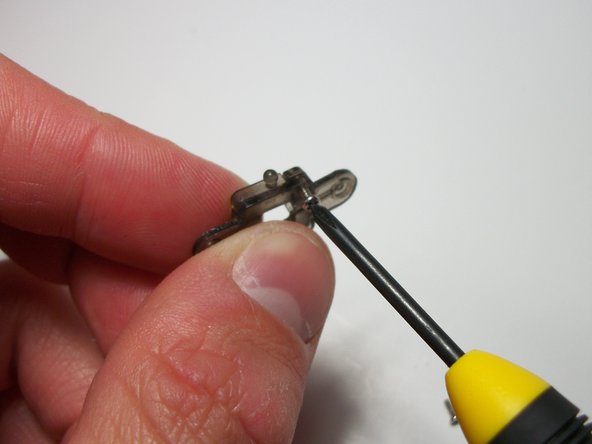
Using tweezers, gently remove the two stabilizing links by pulling straight away from the point of connection.
-
-
Dieser Schritt ist noch nicht übersetzt. Hilf mit, ihn zu übersetzen!
-
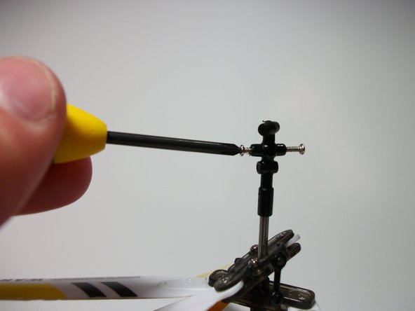
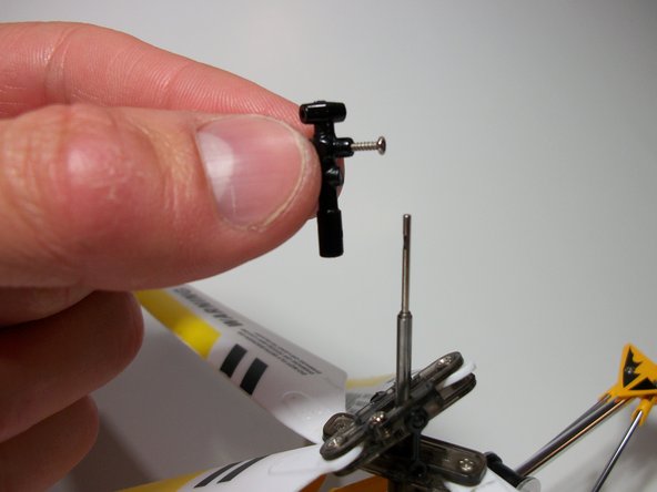
Remove the counterweight bar by removing the screw.
-
One 10.1mm Phillips #0.
-
-
Dieser Schritt ist noch nicht übersetzt. Hilf mit, ihn zu übersetzen!
-
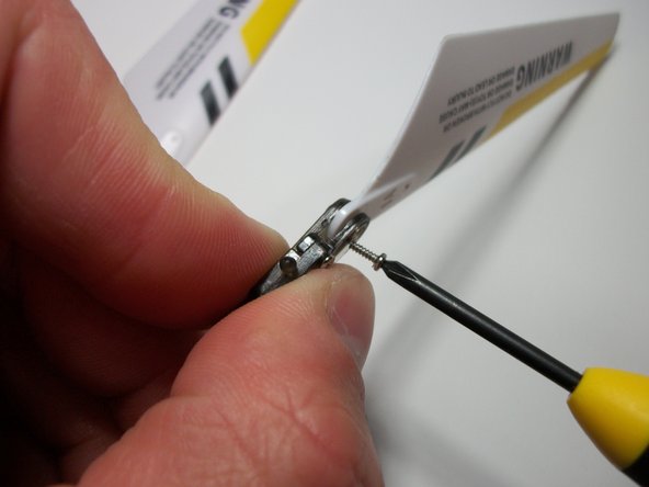
Remove the gyro carriage by removing the following screws:
-
Two 5.6mm Phillips #0.
-
-
-
Dieser Schritt ist noch nicht übersetzt. Hilf mit, ihn zu übersetzen!
-
Gently remove the broken gyro carriage by pulling up.
-
Remove blade assembly by simply sliding it up and off the shaft.
-
-
Dieser Schritt ist noch nicht übersetzt. Hilf mit, ihn zu übersetzen!
-
Again using tweezers gently remove the stabilizing links from the blade carriage by pulling straight away from the point of connection.
-
-
Dieser Schritt ist noch nicht übersetzt. Hilf mit, ihn zu übersetzen!
-
Remove the blades from the blade carriage by removing the following screws:
-
Two 4.7mm Phillips #0.
-
-
Dieser Schritt ist noch nicht übersetzt. Hilf mit, ihn zu übersetzen!
-
Remove the following screws:
-
Two 4.5mm Phillips #0.
-


Rückgängig: Ich habe diese Anleitung nicht absolviert.
7 weitere Nutzer:innen haben diese Anleitung absolviert.
Team

USF Tampa, Team 1-31, Donnelly Fall 2014 Mitglied von USF Tampa, Team 1-31, Donnelly Fall 2014
USFT-DONNELLY-F14S1G31
1 Mitglied
1 Anleitung geschrieben
6 Kommentare
Thank you for this guide! This has fixed the issue and made a 35 year old boy very happy!
Cheers thanks too this page I fixed problem great , Martin
I’m halfway there and grateful for the directions. But I’m not having any luck removing the broken plastic pins from the blade carriage. I’ve tried using a needle but no luck. Did anyone else come up against this?