Diese Version enthält möglicherweise inkorrekte Änderungen. Wechsle zur letzten geprüften Version.
Was du brauchst
-
Dieser Schritt ist noch nicht übersetzt. Hilf mit, ihn zu übersetzen!
-
Remove the four H2 screws from the back of the phone. Do not lose the black rubber rings on the screws.
-
Remove the two H2 screws, on either side of the phone. Do not lose the red seal that are on the screws.
-
Using a prying tool work off the back of the case. Ensuring not to lose the port covers. Be careful to note the position of connector covers. Have the tabs at the end of the connectors in place before clipping the phone completely back together.
-
-
Dieser Schritt ist noch nicht übersetzt. Hilf mit, ihn zu übersetzen!
-
Remove the two black Philips head screws from the battery connector cover.
-
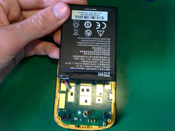
Lift the battery cover away from the logic board
-
-
Dieser Schritt ist noch nicht übersetzt. Hilf mit, ihn zu übersetzen!
-
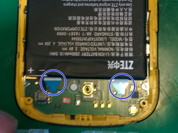
Disconnect the battery connector from the logic board. Do so by inserting a flat tool under the wires on the indicated side and wedging it up off the logic board.
-
Then remove the double sided tape using the blue tabs provided. Simply grab a tab and pull until it comes out tweezers are really good for beginning the process.
-
-
-
Dieser Schritt ist noch nicht übersetzt. Hilf mit, ihn zu übersetzen!
-
Remove two black Phillips head screws and remove the back speaker assembly.
-
-
Dieser Schritt ist noch nicht übersetzt. Hilf mit, ihn zu übersetzen!
-
Disconnect the digitizer cable from is socket, flip the brown clasp up from indicated edge and gently remove the cable.
-
-
Dieser Schritt ist noch nicht übersetzt. Hilf mit, ihn zu übersetzen!
-
Separate the logic board from front display. Apply heat to the front glass to loosen the adhesive, using a prying tool to separate the board. Be careful and move slowly, it is very strong.
-
Be careful to remove the display first from the right side as there are clips along the left side.
-
Ensure not to damage the LCD cable, remove once accessible by releasing the brown clasp from indicated side.
-
-
Dieser Schritt ist noch nicht übersetzt. Hilf mit, ihn zu übersetzen!
-
Carefully remove front speaker from the display assembly with spudger tool, can be accessed from indicated side.
-