Diese Version enthält möglicherweise inkorrekte Änderungen. Wechsle zur letzten geprüften Version.
Was du brauchst
-
Dieser Schritt ist noch nicht übersetzt. Hilf mit, ihn zu übersetzen!
-
Remove the 2 rubber foot pads from the bottom (opposite the hinge) with the small Plastic Opening tool.
-
-
Dieser Schritt ist noch nicht übersetzt. Hilf mit, ihn zu übersetzen!
-
Remove the 10 7.1 mm screws using Phillips #1 screwdriver.
-
-
Dieser Schritt ist noch nicht übersetzt. Hilf mit, ihn zu übersetzen!
-
Loosen the back cover by using a plastic opening tool all the way around the device.
-
-
Dieser Schritt ist noch nicht übersetzt. Hilf mit, ihn zu übersetzen!
-
Remove the back cover by gently lifting up on one side of the device.
-
-
Dieser Schritt ist noch nicht übersetzt. Hilf mit, ihn zu übersetzen!
-
Remove the tape holding the speaker wire to the battery on both sides using a small opening tool.
-
-
Dieser Schritt ist noch nicht übersetzt. Hilf mit, ihn zu übersetzen!
-
Remove the 4 Phillips 3.2 mm screws holding the battery in place, with the Phillips #1 screwdriver.
-
-
Dieser Schritt ist noch nicht übersetzt. Hilf mit, ihn zu übersetzen!
-
To disconnect the wire from the mother board, gently press down with the flat end of Spudger and pull on the wire.
-
-
-
Dieser Schritt ist noch nicht übersetzt. Hilf mit, ihn zu übersetzen!
-
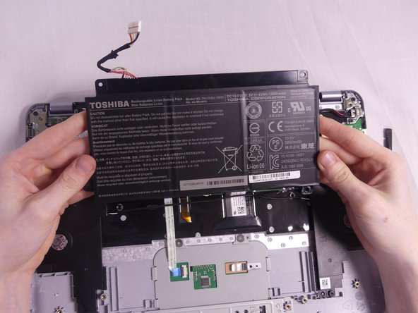
Remove the battery by gently pulling on the bottom corners.
-
-
Dieser Schritt ist noch nicht übersetzt. Hilf mit, ihn zu übersetzen!
-
Unscrew the 4 Phillip screws using a Phillips # 1 Screwdriver.
-
-
Dieser Schritt ist noch nicht übersetzt. Hilf mit, ihn zu übersetzen!
-
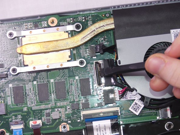
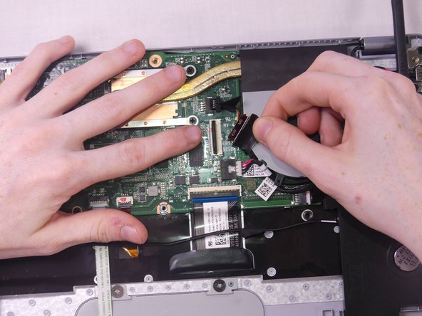
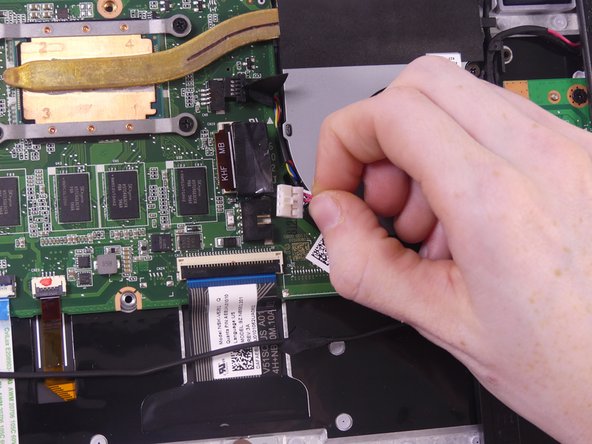
The top wire is the fan's wire. Remove it by pulling it from the motherboard.
-
-
Dieser Schritt ist noch nicht übersetzt. Hilf mit, ihn zu übersetzen!
-
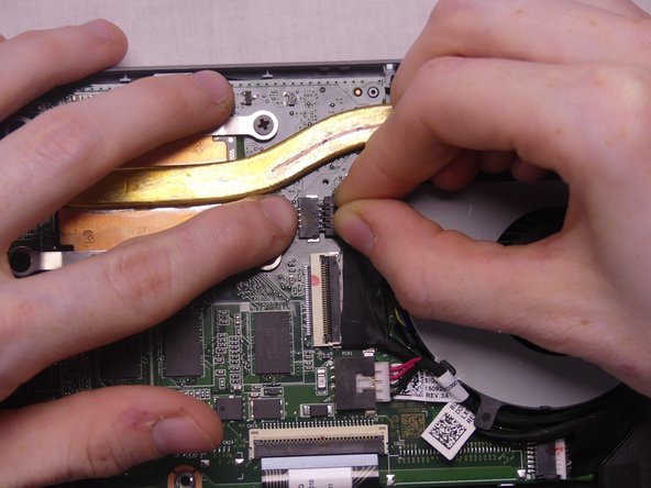
To remove the Wifi PCB wire lift up the hinged flap with your finger or with the aid of the spudger tool.
-
After the flap is lifted, pull the wire up out of the connector socket.
-
-
Dieser Schritt ist noch nicht übersetzt. Hilf mit, ihn zu übersetzen!
-
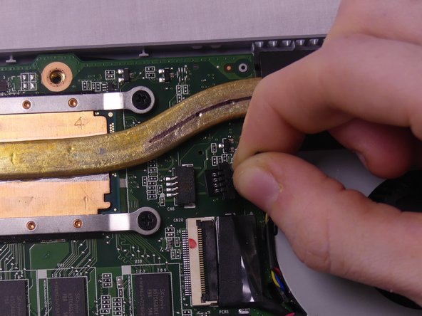
Remove the headphone jack wire by pulling it out of the connector socket.
-
-
Dieser Schritt ist noch nicht übersetzt. Hilf mit, ihn zu übersetzen!
-
Remove the Phillip 3.6 mm screw from the fan using a Phillips #1 screwdriver.
-
-
Dieser Schritt ist noch nicht übersetzt. Hilf mit, ihn zu übersetzen!
-
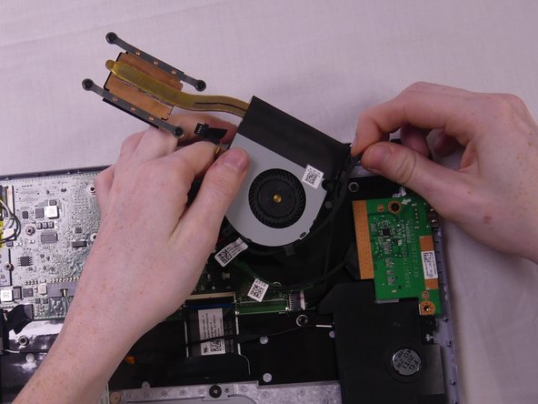
Lift up on the metal plate that hold the screws to start removing the fan.
-
-
Dieser Schritt ist noch nicht übersetzt. Hilf mit, ihn zu übersetzen!
-
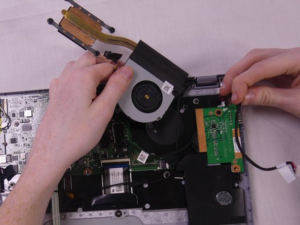
Once lifted, you will notice that there are two wires tucked under plastic tunnels on the right side of the fan. Remove these wires.
-
Once the wires are removed the fan should be removed entirely.
-
-
Dieser Schritt ist noch nicht übersetzt. Hilf mit, ihn zu übersetzen!
-
The WiFi PCB is located next to the fan.
-
-
Dieser Schritt ist noch nicht übersetzt. Hilf mit, ihn zu übersetzen!
-
Remove the Phillips 3.7 mm screw using a Phillips #1 screwdriver.
-
-
Dieser Schritt ist noch nicht übersetzt. Hilf mit, ihn zu übersetzen!
-
Gently remove the WiFi PCB by pulling upward.
-


Team

USF Tampa, Team S1-G121, Cagle Fall 2017 Mitglied von USF Tampa, Team S1-G121, Cagle Fall 2017
USFT-CAGLE-F17S1G121
3 Mitglieder
14 Anleitungen geschrieben
Ein Kommentar
The article has some mistakes, namely, this isn’t the WiFi / WLAN, it is a USB port and card reader slot PCB. I came to iFixIt to double-check the part to upgrade to WiFi 6 (ax). Once you fix the part name, the article is good! The part number DA0BUITH8D0 is what to search for when trying to buy one. I didn’t need one, but looked it up just the same, there are not a ton of these out there and I would probably just resort to a USB reader.