Diese Version enthält möglicherweise inkorrekte Änderungen. Wechsle zur letzten geprüften Version.
Was du brauchst
-
Dieser Schritt ist noch nicht übersetzt. Hilf mit, ihn zu übersetzen!
-
Locate the two sliding locks indicated in the photo.
-
Slide the right lock (labeled "1") to the right. It will remain in the unlocked position.
-
Slide the left lock (labeled "2") to the left and hold it in place.
-
-
Dieser Schritt ist noch nicht übersetzt. Hilf mit, ihn zu übersetzen!
-
While holding the left lock, place your finger in the indentation next to the battery and lift the battery out.
-
-
Dieser Schritt ist noch nicht übersetzt. Hilf mit, ihn zu übersetzen!
-
Remove the four screws indicated in the photos using a Phillips 00 Screwdriver. Left to right: 6mm button-head, 3mm flat-head, 6mm button-head, 6mm button-head.
-
-
Dieser Schritt ist noch nicht übersetzt. Hilf mit, ihn zu übersetzen!
-
With your hands, grasp the speaker cover on the edge nearest to the screen.
-
Pry the speaker cover upward.
-
-
Dieser Schritt ist noch nicht übersetzt. Hilf mit, ihn zu übersetzen!
-
Remove the speaker cover. Your laptop will look like this photo when the speaker cover has been removed.
-
-
Dieser Schritt ist noch nicht übersetzt. Hilf mit, ihn zu übersetzen!
-
Remove the two 4mm flat-head screws indicated in the photo.
-
-
Dieser Schritt ist noch nicht übersetzt. Hilf mit, ihn zu übersetzen!
-
Slightly lift and ease the keyboard forward, toward the screen, until the tabs clear the case.
-
When all the tabs are free, slowly lift the bottom of the keyboard while keeping the top of the keyboard angled down. Continue to carefully rotate the keyboard over until you can access the ribbon cable that is still connecting it to the computer.
-
-
Dieser Schritt ist noch nicht übersetzt. Hilf mit, ihn zu übersetzen!
-
The Ribbon Cable must be disconnected here to release the keyboard.
-
Using a plastic splunger or the tip of your screwdriver gently push upward on the two black tabs securing the connection.
-
When the black plastic bar running across the cable is unseated you can slowly and carefully pull the ribbon cable free.
-
You can now lift and remove the keyboard.
-
-
Dieser Schritt ist noch nicht übersetzt. Hilf mit, ihn zu übersetzen!
-
Locate the gray wire on the right.
-
Detach the white end by gently pulling each socket away from the other.
-
-
Dieser Schritt ist noch nicht übersetzt. Hilf mit, ihn zu übersetzen!
-
On the left, locate the black and white wires with gold tips on the end.
-
Pull up on the wires to detach them.
-
-
-
Dieser Schritt ist noch nicht übersetzt. Hilf mit, ihn zu übersetzen!
-
Locate the thick tan cord on the left.
-
Slide the tan cord as shown to detach it.
-
-
Dieser Schritt ist noch nicht übersetzt. Hilf mit, ihn zu übersetzen!
-
On the right, locate the thick black wire with the white rectangular end.
-
Pull up on it to detach it.
-
-
Dieser Schritt ist noch nicht übersetzt. Hilf mit, ihn zu übersetzen!
-
Remove the four 8mm button-head screws that are located in the top right (2) and top left corners (2) of the front cover. Use a Phillips 00 Screwdriver.
-
-
Dieser Schritt ist noch nicht übersetzt. Hilf mit, ihn zu übersetzen!
-
Once all the wires are detached and screws are removed, pull up on the monitor to remove it.
-
-
Dieser Schritt ist noch nicht übersetzt. Hilf mit, ihn zu übersetzen!
-
Locate the screws that are shown in the image.
-
Remove the fourteen 6mm button-head screws with a Phillips 00 Screwdriver.
-
-
Dieser Schritt ist noch nicht übersetzt. Hilf mit, ihn zu übersetzen!
-
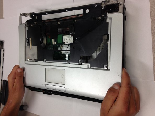
Lift up on the front cover to remove it.
-
-
Dieser Schritt ist noch nicht übersetzt. Hilf mit, ihn zu übersetzen!
-
Locate the USB 2.0 cable on the bottom right corner of the laptop.
-
-
Dieser Schritt ist noch nicht übersetzt. Hilf mit, ihn zu übersetzen!
-
Locate the white slot on the left side of the USB 2.0 wire.
-
Carefully detach the wire by pulling the cable to the right of the slot.
-
-
Dieser Schritt ist noch nicht übersetzt. Hilf mit, ihn zu übersetzen!
-
Locate the 6mm flat-head screw in the top right corner of the bottom of the laptop.
-
Remove this screw with the Phillips 00 Screwdriver.
-
-
Dieser Schritt ist noch nicht übersetzt. Hilf mit, ihn zu übersetzen!
-
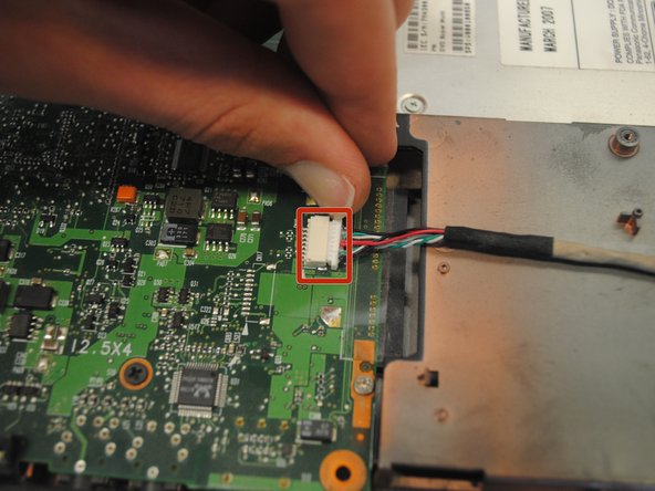
Locate and remove the white connector that is .75 inches wide.
-
-
Dieser Schritt ist noch nicht übersetzt. Hilf mit, ihn zu übersetzen!
-
Locate and remove the smaller white connector (far right) and any tape that is holding it down.
-
-
Dieser Schritt ist noch nicht übersetzt. Hilf mit, ihn zu übersetzen!
-
Remove any tape that is still covering the fan.
-
Remove the fan.
-
-
Dieser Schritt ist noch nicht übersetzt. Hilf mit, ihn zu übersetzen!
-
Locate the 4mm flat-head screw. Remove it using the Phillips 00 Screwdriver.
-
-
Dieser Schritt ist noch nicht übersetzt. Hilf mit, ihn zu übersetzen!
-
Turn the computer over.
-
Locate the optical drive on the right.
-
-
Dieser Schritt ist noch nicht übersetzt. Hilf mit, ihn zu übersetzen!
-
Using two fingers, slide the optical drive toward the edge of the computer.
-
Continue to slide the optical drive until it can be removed from the computer.
-
-
Dieser Schritt ist noch nicht übersetzt. Hilf mit, ihn zu übersetzen!
-
Locate the two black and red wires on each side of the motherboard.
-
Slowly pull back on the cables away from the motherboard to detach them from their connector slots.
-
-
Dieser Schritt ist noch nicht übersetzt. Hilf mit, ihn zu übersetzen!
-
Pinch the plastic cable horizontally and pull it away from the socket in order to remove the cable connecting the motherboard to the speaker cover buttons.
-
-
Dieser Schritt ist noch nicht übersetzt. Hilf mit, ihn zu übersetzen!
-
Locate the black wire next to optical drive and gently pull it away from the socket to remove it.
-
-
Dieser Schritt ist noch nicht übersetzt. Hilf mit, ihn zu übersetzen!
-
Remove the six 4mm flat-head screws with a Phillips 00 Screwdriver.
-
-
Dieser Schritt ist noch nicht übersetzt. Hilf mit, ihn zu übersetzen!
-
Place one hand on the side with the optical drive and one hand on the side with the fan.
-
Pull the motherboard away from the main frame at a slightly upward angle.
-


Rückgängig: Ich habe diese Anleitung nicht absolviert.
7 weitere Nutzer:innen haben diese Anleitung absolviert.
Team

Cal Poly, Team 17-6, Regan Spring 2013 Mitglied von Cal Poly, Team 17-6, Regan Spring 2013
CPSU-REGAN-S13S17G6
5 Mitglieder
33 Anleitungen geschrieben