Diese Version enthält möglicherweise inkorrekte Änderungen. Wechsle zur letzten geprüften Version.
Was du brauchst
-
Dieser Schritt ist noch nicht übersetzt. Hilf mit, ihn zu übersetzen!
-
Power down the computer and unplug the power adapter.
-
-
Dieser Schritt ist noch nicht übersetzt. Hilf mit, ihn zu übersetzen!
-
Flip the laptop upside down. Locate the two latches on both sides of the battery.
-
-
Dieser Schritt ist noch nicht übersetzt. Hilf mit, ihn zu übersetzen!
-
Slide the latch on the right outwards, releasing the lock. The latch stays unlocked once moved.
-
Simultaneously slide the latch on the left outwards while pulling the battery towards you.
-
-
Dieser Schritt ist noch nicht übersetzt. Hilf mit, ihn zu übersetzen!
-
Remove the single captive screw on the back panel with your Phillips #1 screwdriver.
-
-
Dieser Schritt ist noch nicht übersetzt. Hilf mit, ihn zu übersetzen!
-
Pry the removal tab up. You will feel and hear the first clip release, popping up slightly.
-
Work your way around the border of the panel, releasing the rest of the clips.
-
Once all clips are released, lift the cover up and pull towards you.
-
-
Dieser Schritt ist noch nicht übersetzt. Hilf mit, ihn zu übersetzen!
-
Slide the hard drive to the left, using the silver tab.
-
Pull up the silver tab, removing the hard drive from the slot.
-
-
Dieser Schritt ist noch nicht übersetzt. Hilf mit, ihn zu übersetzen!
-
Using your fingers, spread the spring tabs holding the top stick of RAM in place.
-
Once the tabs are spread apart, the stick of RAM will pop up.
-
Remove the first stick of RAM by pulling out along the same angle the RAM stick springs up.
-
-
Dieser Schritt ist noch nicht übersetzt. Hilf mit, ihn zu übersetzen!
-
Repeat the same procedure to remove the second stick of RAM.
-
-
Dieser Schritt ist noch nicht übersetzt. Hilf mit, ihn zu übersetzen!
-
Pry under the plastic strip, starting on the top right side of the key board with a Heavy Duty Spudger.
-
Once the first corner is raised, use your hand pulling upwards and release the rest of the strip.
-
-
-
Dieser Schritt ist noch nicht übersetzt. Hilf mit, ihn zu übersetzen!
-
Remove the first 3mm screw with the Phillips #1 screwdriver.
-
Remove the next three 3mm screws.
-
-
Dieser Schritt ist noch nicht übersetzt. Hilf mit, ihn zu übersetzen!
-
Use the pointed end of the Heavy-Duty Spudger and push the pins toward the screen, leaving them in this position.
-
Carefully slide the connector out of the port.
-
-
Dieser Schritt ist noch nicht übersetzt. Hilf mit, ihn zu übersetzen!
-
Remove the following screws with a Phillips #1 screwdriver.
-
Seventeen 5mm screws (recessed)
-
Three 2mm screws in the battery bay (flush-mounted)
-
Single 5mm screw does not need removal unless working on the screen
-
-
Dieser Schritt ist noch nicht übersetzt. Hilf mit, ihn zu übersetzen!
-
Remove five 5mm screws with the screwdriver.
-
-
Dieser Schritt ist noch nicht übersetzt. Hilf mit, ihn zu übersetzen!
-
Locate the trackpad connector.
-
Pull the ribbon from the connector.
-
-
Dieser Schritt ist noch nicht übersetzt. Hilf mit, ihn zu übersetzen!
-
Pry under the top case housing along the perimeter with a plastic opening tool.
-
-
Dieser Schritt ist noch nicht übersetzt. Hilf mit, ihn zu übersetzen!
-
Remove the screen input wire from the port.
-
-
Dieser Schritt ist noch nicht übersetzt. Hilf mit, ihn zu übersetzen!
-
Slide the metal power button connector out of its port, allowing the black wire to be moved from under it.
-
-
Dieser Schritt ist noch nicht übersetzt. Hilf mit, ihn zu übersetzen!
-
Lift the black connector with tweezers and repeat the same action for the white connector.
-
-
Dieser Schritt ist noch nicht übersetzt. Hilf mit, ihn zu übersetzen!
-
The screen is attached with two hinges on both sides of the laptop.
-
Remove the three 5mm screws (two on the left hinge, one on the right hinge) using a screwdriver.
-
Remove brass fitting held in place by removing the 5mm screw circled in yellow in step 15.
-
-
Dieser Schritt ist noch nicht übersetzt. Hilf mit, ihn zu übersetzen!
-
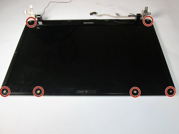
Remove the 6 rubber tabs on the housing using a metal Spudger.
-
Remove the six 6mm screws holding the housing.
-
-
Dieser Schritt ist noch nicht übersetzt. Hilf mit, ihn zu übersetzen!
-
Use the plastic opening tool to pry the screen housing.
-
-
Dieser Schritt ist noch nicht übersetzt. Hilf mit, ihn zu übersetzen!
-
Remove two 5mm screws using a screwdriver. There is one screw at each hinge.
-
Remove white wire from the perimeter of the plastic housing.
-
-
Dieser Schritt ist noch nicht übersetzt. Hilf mit, ihn zu übersetzen!
-
Disconnect the webcam data wire using tweezers.
-
-
Dieser Schritt ist noch nicht übersetzt. Hilf mit, ihn zu übersetzen!
-
Remove the three 2.5mm screws on each side of the screen casing with a screwdriver.
-
The two metal casings can now be removed.
-


Rückgängig: Ich habe diese Anleitung nicht absolviert.
2 weitere Nutzer:innen haben diese Anleitung absolviert.
Team

UC Davis, Team 2-2, Oliver Fall 2016 Mitglied von UC Davis, Team 2-2, Oliver Fall 2016
UCD-OLIVER-F16S2G2
5 Mitglieder
10 Anleitungen geschrieben