Diese Version enthält möglicherweise inkorrekte Änderungen. Wechsle zur letzten geprüften Version.
Was du brauchst
-
Dieser Schritt ist noch nicht übersetzt. Hilf mit, ihn zu übersetzen!
-
Remove the two 7 mm Phillips #1 screws that hold the battery in place.
-
-
Dieser Schritt ist noch nicht übersetzt. Hilf mit, ihn zu übersetzen!
-
Remove the ten 7 mm Phillips #1 screws that secure the back cover.
-
-
Dieser Schritt ist noch nicht übersetzt. Hilf mit, ihn zu übersetzen!
-
Wedge the tip of a plastic opening tool between the back cover and the metal frame.
-
Twist the plastic opening tool, while wedged, in order to release the retaining tabs from the frame.
-
Repeat these steps in a circular pattern around the laptop to release all retaining tabs.
-
-
Dieser Schritt ist noch nicht übersetzt. Hilf mit, ihn zu übersetzen!
-
Once all retaining tabs are released from the frame, you can pull up on the back cover to remove it.
-
-
Dieser Schritt ist noch nicht übersetzt. Hilf mit, ihn zu übersetzen!
-
Remove the two 3.5 mm Phillips #1 screws that hold the cooling fan in place.
-
-
-
Dieser Schritt ist noch nicht übersetzt. Hilf mit, ihn zu übersetzen!
-
Wedge the flat end of the spudger between the connector and its socket.
-
Twist back and forth in order to pry the connector loose from its socket.
-
-
Dieser Schritt ist noch nicht übersetzt. Hilf mit, ihn zu übersetzen!
-
Lift up on the cooling fan to remove it from the laptop.
-
-
Dieser Schritt ist noch nicht übersetzt. Hilf mit, ihn zu übersetzen!
-
Remove the three 4 mm Phillips #1 screws holding the motherboard in place.
-
-
Dieser Schritt ist noch nicht übersetzt. Hilf mit, ihn zu übersetzen!
-
Remove the four 4 mm Phillips #1 screws mounting the heat sink to the motherboard.
-
-
Dieser Schritt ist noch nicht übersetzt. Hilf mit, ihn zu übersetzen!
-
Gently lift on either side of the heat sink to separate it from the laptop.
-
-
Dieser Schritt ist noch nicht übersetzt. Hilf mit, ihn zu übersetzen!
-
On all ZIF (Zero Insertion Force) connectors, use a spudger to lift the lock.
-
Use tweezers to pull on the designated pull tab to remove each ZIF connector.
-
-
Dieser Schritt ist noch nicht übersetzt. Hilf mit, ihn zu übersetzen!
-
On all No-Fuss Ribbon Cable Connectors use tweezers, on the designated tabs, to remove them.
-
-
Dieser Schritt ist noch nicht übersetzt. Hilf mit, ihn zu übersetzen!
-
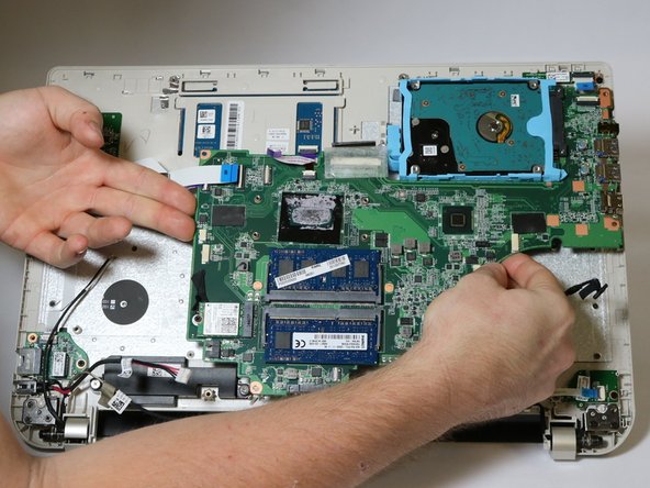
Lift on the motherboard from the USB port area while pulling the frame away from motherboard.
-
-
Dieser Schritt ist noch nicht übersetzt. Hilf mit, ihn zu übersetzen!
-
Once all connectors are separated from the motherboard and the USB port area is freed, carefully lift on either side of the motherboard to remove it.
-
-
Dieser Schritt ist noch nicht übersetzt. Hilf mit, ihn zu übersetzen!
-
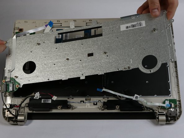
Remove the twenty-seven 2 mm Phillips #0 screws that secure the keyboard retaining plate.
-
-
Dieser Schritt ist noch nicht übersetzt. Hilf mit, ihn zu übersetzen!
-
Carefully lift the keyboard retaining plate away from the laptop making sure not to damage any connectors.
-
-
Dieser Schritt ist noch nicht übersetzt. Hilf mit, ihn zu übersetzen!
-
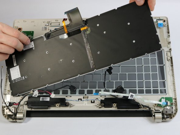
Lift up on the keyboard to remove it from the laptop.
-


Rückgängig: Ich habe diese Anleitung nicht absolviert.
4 weitere Nutzer:innen haben diese Anleitung absolviert.
Team

USF Tampa, Team 2-1, Blackwell Fall 2016 Mitglied von USF Tampa, Team 2-1, Blackwell Fall 2016
USFT-BLACKWELL-F16S2G1
4 Mitglieder
7 Anleitungen geschrieben