Diese Version enthält möglicherweise inkorrekte Änderungen. Wechsle zur letzten geprüften Version.
Was du brauchst
-
Dieser Schritt ist noch nicht übersetzt. Hilf mit, ihn zu übersetzen!
-
Firmly press the SIM card removal tool into the hole located at the top of the phone to eject the SIM card tray from the slot.
-
-
Dieser Schritt ist noch nicht übersetzt. Hilf mit, ihn zu übersetzen!
-
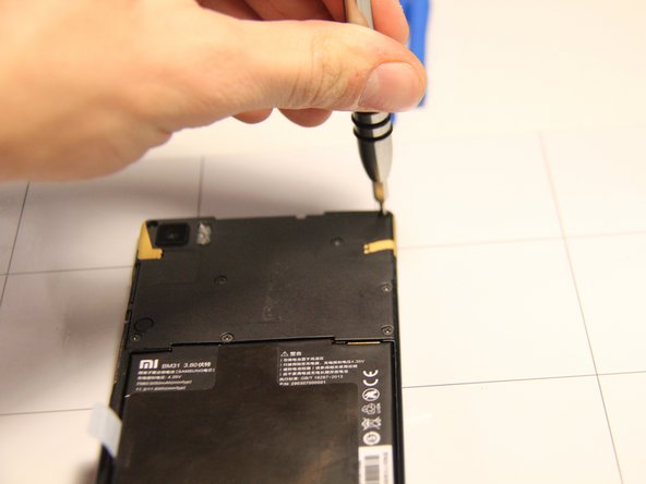
Remove the two Phillips head screws located at the top of the phone on either side where the SIM card was ejected.
-
-
Dieser Schritt ist noch nicht übersetzt. Hilf mit, ihn zu übersetzen!
-
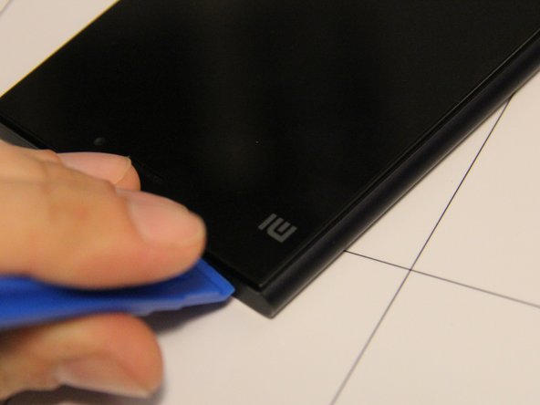
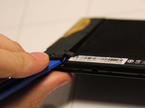
Insert a pry tool into the upper edge of the phone, where there is a small gap between screen and frame of the phone to begin separating the screen from the rest of the phone.
-
-
Dieser Schritt ist noch nicht übersetzt. Hilf mit, ihn zu übersetzen!
-
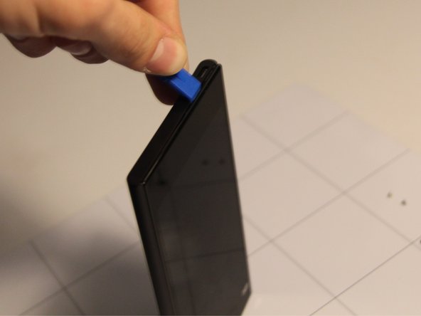
Once the pry tool has been inserted into the phone, slide it around the perimeter of the phone while gently lifting until the screen panel and back panel of the phone separate.
-
-
Dieser Schritt ist noch nicht übersetzt. Hilf mit, ihn zu übersetzen!
-
The back of the phone should now be separated from the screen.
-
-
Dieser Schritt ist noch nicht übersetzt. Hilf mit, ihn zu übersetzen!
-
Place the front panel screen side down with the camera at the top.
-
Remove these six Phillips head screws located at the upper half of the phone.
-
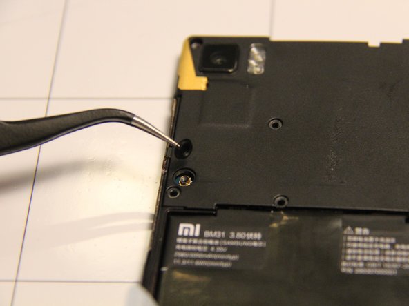
This screw is located under an orange sticker at the top right corner of the panel. The sticker can be removed with a pair of tweezers, then remove that Phillips head screw.
-
-
Dieser Schritt ist noch nicht übersetzt. Hilf mit, ihn zu übersetzen!
-
Next, remove these three screws located at the bottom of the back panel.
-
-
Dieser Schritt ist noch nicht übersetzt. Hilf mit, ihn zu übersetzen!
-
Using tweezers, remove the rubber dust cover on the back panel of the phone.
-
-
-
Dieser Schritt ist noch nicht übersetzt. Hilf mit, ihn zu übersetzen!
-
Remove the plastic cover on the bottom of the back panel by inserting the pry tool at the edge and gently lifting.
-
-
Dieser Schritt ist noch nicht übersetzt. Hilf mit, ihn zu übersetzen!
-
Remove the upper plastic cover from the back panel by inserting the pry tool into the upper edge and gently lifting.
-
-
Dieser Schritt ist noch nicht übersetzt. Hilf mit, ihn zu übersetzen!
-
Using a spudger, remove the small ribbon cable that is connected to the battery.
-
-
Dieser Schritt ist noch nicht übersetzt. Hilf mit, ihn zu übersetzen!
-
Remove the battery by gripping and pull up on the "Battery Removal" tab attached to the left side of the battery on the back panel.
-
-
Dieser Schritt ist noch nicht übersetzt. Hilf mit, ihn zu übersetzen!
-
The battery is now removed from the panel.
-
-
Dieser Schritt ist noch nicht übersetzt. Hilf mit, ihn zu übersetzen!
-
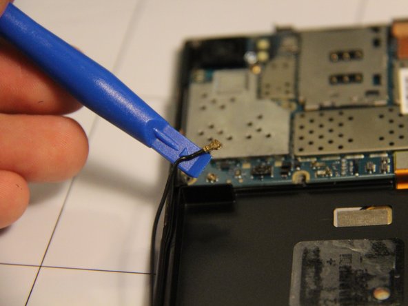
Disconnect the antenna wire that is attached to the lower left side of the motherboard using the pry tool.
-
-
Dieser Schritt ist noch nicht übersetzt. Hilf mit, ihn zu übersetzen!
-
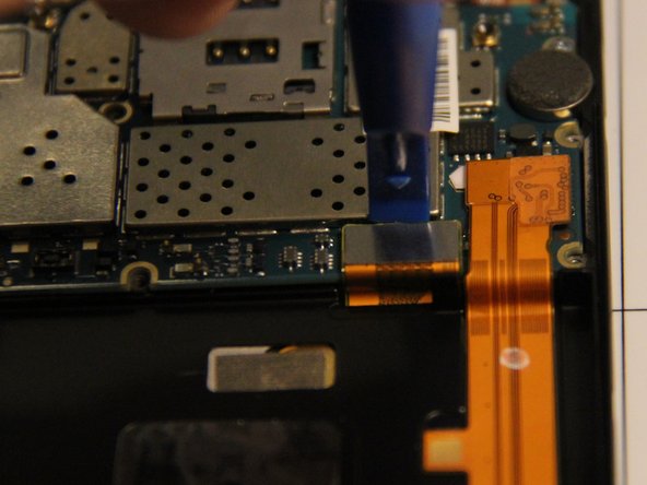
Use a pry tool to separate the LCD display cable from the motherboard. The cable connects to the motherboard as a rectangular metallic piece at the bottom right of the motherboard.
-
-
Dieser Schritt ist noch nicht übersetzt. Hilf mit, ihn zu übersetzen!
-
Disconnect the gold ribbon cable for the LCD display by gently inserting the pry tool under the wide end and lifting up.
-
-
Dieser Schritt ist noch nicht übersetzt. Hilf mit, ihn zu übersetzen!
-
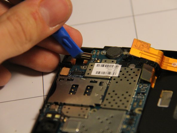
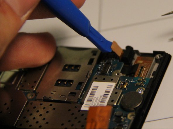
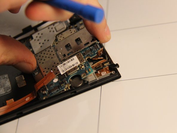
Separate a cable ribbon from the top right of the motherboard by gently inserting the pry tool under the rectangular metallic piece and lifting.
-
-
Dieser Schritt ist noch nicht übersetzt. Hilf mit, ihn zu übersetzen!
-
Separate a cable ribbon from the top right of the motherboard - near the cable from the previous step - by gently inserting the pry tool under the rectangular metallic piece and lifting.
-
-
Dieser Schritt ist noch nicht übersetzt. Hilf mit, ihn zu übersetzen!
-
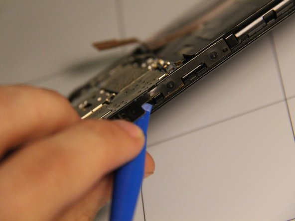
Using a pry tool, gently lift the side control buttons assembly away from the case. They should be loosely connected to the motherboard.
-
-
Dieser Schritt ist noch nicht übersetzt. Hilf mit, ihn zu übersetzen!
-
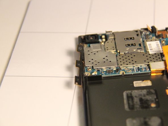
Remove the motherboard from the panel carefully. Use the pry tool as a lever from the top of the panel and lift if from that side.
-
-
Dieser Schritt ist noch nicht übersetzt. Hilf mit, ihn zu übersetzen!
-
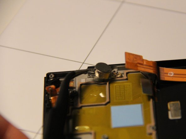
The motherboard has now been successfully removed.
-
-
Dieser Schritt ist noch nicht übersetzt. Hilf mit, ihn zu übersetzen!
-
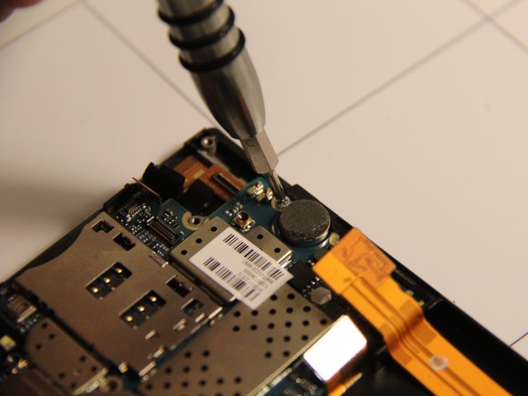
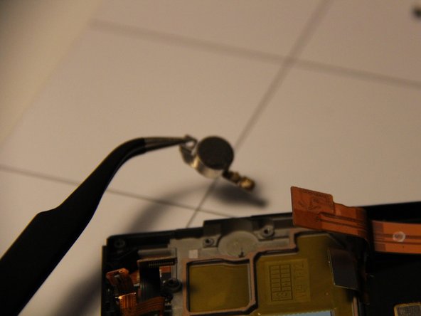
With the motherboard removed you can use tweezers to remove the vibrator rather easily.
-


Rückgängig: Ich habe diese Anleitung nicht absolviert.
3 weitere Nutzer:innen haben diese Anleitung absolviert.
Team

USF Tampa, Team 1-5, Remmell Fall 2015 Mitglied von USF Tampa, Team 1-5, Remmell Fall 2015
USFT-REMMELL-F15S1G5
4 Mitglieder
6 Anleitungen geschrieben