Einleitung
Das obere metallische Abschirmblech schützt das Logic Board vor elektromagnetischen Interferenzen.
Was du brauchst
-
-
Drehe die Verschlussschraube des Akkufachs mit einer Münze um 90° im Uhrzeigersinn.
-
Hebe den Akku aus dem Computer.
-
-
-
Ziehe die Laschen, mit denen die Tastatur eingeklinkt ist, zu dir, bis sich die Tastatur löst.
-
Wenn sich die Tastatur doch nicht ablöst, dann drehe die Befestigungsschraube der Tastatur mit einem kleinen Flachschraubendreher um 180° in die andere Richtung und probiere es erneut.
-
Klappe die Tastatur vom Display weg und lege sie mit den Tasten nach unten auf das Trackpad.
-
-
-
Drücke die Kabelklammer zur AirPort-Karte hin und ziehe sie von der RAM-Abschirmung weg.
-
-
-
Fasse die durchsichtige Kunstofflasche an der AirPort-Karte an und ziehe sie nach rechts.
-
-
-
Halte die AirPort-Karte mit einer Hand fest und entferne das Antennenkabel mit der anderen Hand.
-
-
-
Entferne die beiden 2,5 mm Kreuzschlitzschrauben, mit denen die RAM-Abschirmung befestigt ist.
-
-
-
Fasse die Metallhalterung oben auf der RAM-Abschirmung und ziehe sie hoch, bis sich die Abschirmung ablöst.
-
-
-
Fasse das Tastaturkabel so nahe wie möglich am Stecker und ziehe es vom Logic Board ab.
I feel this step needs clarification: Are just lifting the cable away from the shield, or are we removing the cable entirely?
-
-
-
So ungefähr sollte dein Laptop aussehen.
Remove the two long screws along the back edge, and the shorter screw in the middle. Torx T-8. Pry up the rubber feet, and unscrew the three Phillips screws that hold the feet in place. Putting the silver collars back requires a little bit of fiddling to get them oriented correctly so they sit flush with the bottom case.
-
-
-
Entferne die drei Gummifüße mit einer Nadel (oder einem anderen spitzen Werkzeug) vom unteren Gehäuse.
-
-
-
Entferne die jetzt freigelegten drei 5,2 mm Kreuzschlitzschrauben.
this should be after step 12 no?
This should be step 3.
-
-
-
Entferne die drei Metallringe, mit denen die Gummifüße eingefasst waren, mit einem Spudger oder einem kleinen Flachschraubendreher.
-
-
-
Entferne die eine 10 mm und die beiden 20 mm Schrauben mit einem 2 mm Sechskantschlüssel. Du kannst auch einen Torx T8 Schraubendreher benutzen.
FYI, the two screws at the top of this picture are longer than the one in the middle of the case. Don't mix them up!
Two of the hex screws here got stripped. Please, replace them ASAP and I would recommend not putting them back just to not risk making them stuck. I spent 30 minutes trying to get those two out.
-
-
-
-
Entferne die beiden 4,2 mm Kreuzschlitzschrauben an jeder Seite der Akkukontakte.
-
-
-
Atme tief durch, jetzt liegen Herausforderungen vor dir. Wir versprechen aber, dass das untere Gehäuse frei wird.
-
Drücke die dünnen Ränder am unteren Gehäuse, die das Akkufach umfassen, nach innen, bis sie sich von ihren Rasten ablösen. Hebe sie dann nach oben, um diese Ecke des unteren Gehäuses zu befreien.
-
-
-
An der Wand des Akkufachs ist ein Schlitz, in dem das untere Gehäuse festgeklemmt ist. Heble den unteren Rand des Schlitzes mit einem kleinen Flachschraubendreher heraus und ziehe das untere Gehäuse nach oben, bis sich der Schlitz von den Rasten löst.
If your iBook's been opened many times (Like mine has been) then this piece may be broken.
If it's cracked down the middle or a little off, what you'll want to do is use your bent paperclip from a few steps later (or another screwdriver) and pull the second piece away from the shell when you start lifting. should pull right out
-
-
-
Schiebe einen Spudger in der Fuge zwischen dem oberen und unteren Gehäuse auf der Vorderseite des Computers entlang, um die Rasten zu lösen, mit denen das untere Gehäuse befestigt ist. Ziehe das untere Gehäuse hoch und hilf mit dem Spudger nach, bis du ein dreifaches Klicken hörst.
-
-
-
Schiebe den Spudger um die vordere rechte Ecke herum. Auf der Seite mit den Anschlüsse befinden sich zwei Rasten, eine nahe an der vorderen Ecke, die andere am Audioanschluss.
isn’t this step out of order? It belongs much later I think
This should be step 4.
-
-
-
Wenn die Vorderseite und die beiden Seiten des unteren Gehäuses frei sind, dann drehe den Computer mit der Rückseite zu dir. Ziehe das untere Gehäuse hoch und zu dir hin, bis sich die Rasten an der Rückseite lösen. (Es hilft eventuell, wenn du das Gehäuse dabei ein wenig auf und ab bewegst).
Be aware that you may need to use a spudger at the front of the computer to separate the metal shield from the bottom case.
-
-
-
Entferne die beiden eingefetteten Federn mit den weißen Plastikkappen auf jeder Seite der Akkukontakte.
Clean the springs and put them back, hopefully without breaking the small plastic pieces on the top of each spring. One of mine broke off and the other one was already missing. Poor design.
-
-
-
Entferne folgende vier Kreuzschlitzschrauben an der Unterseite des Computers:
-
Zwei 3 mm Kreuzschlitzschrauben an der linken Seite.
-
Eine 4,5 mm Kreuzschlitzschraube in der Nähe des Verschlussmechanismus. (Diese Schraube fehlt möglicherweise bei 800 MHz-Modellen)
-
Eine 14,2 mm Kreuzschlitzschraube nahe an der vorderen rechten Ecke.
This photo is a little confusing. The shield should be off, which would show the correct positions of the yellow and orange screws. (The orange circle is in the wrong place.) Furthermore, these screws don't need to be removed at this stage (they hold the logic board to the frame). And finally, on my 800 MHz machine, BOTH these screws are 6 mm in length.
Zitat von commenter:
This photo is a little confusing. The shield should be off, which would show the correct positions of the yellow and orange screws. (The orange circle is in the wrong place.) Furthermore, these screws don't need to be removed at this stage (they hold the logic board to the frame). And finally, on my 800 MHz machine, BOTH these screws are 6 mm in length.
The two red screws and the orange screw have to be removed (iBook G3 600 MHz).
On my 800, the yellow screw is a 6mm Phillips with a wide head.
-
-
-
Öffne den Einschub des optischen Laufwerks mit einer aufgebogenen Büroklammer.
-
-
-
Ziehe das optische Laufwerk soweit heraus, dass du an die Kreuzschlitzschraube in der Nähe des Akkufachs heran kommst. Drehe sie heraus.
i think that we can leave that one out on re-assembly
If you fully extend the tray it's fairly easy to get to the screw by going inside the rails. And grab it with tweezers.
When re-installing use something sticky on your screwdriver to hold the screw in place, or it's never going in. The sleep magnet is nasty at grabbing your screw and pulling it away. (Doesn't hurt to have something sticky on it for taking it out too...)
If you're doing this type of work, what's wonderful is to have a set of technicians magnetic drivers. I have a set of twelve that are about 6"long, and very skinny. Phillips 1, 0, 00, & 000 . . . Torx 6, 7, 8, 9, & 10 . . . and slotted 5/64", 3/32", & 1/8". I wish I could remember where I got them, but you could probably Google it. One of the smaller magnetic Phillips was perfect for removal AND replacing this screw. A word of CAUTION, though . . . probably best to keep any magnetic tools away from sensitive components on the PC board.
To anyone that’s absolutely stuck: there is a little slot along the drive where the screwdriver fits in. I didn’t know this for at least 3 times I took apart this computer, and finding this now has helped me sooooo much.
-
-
-
Ziehe das optische Laufwerk noch etwas weiter heraus, bis du an die zweite Kreuzschlitzschraube nahe an der Stromversorgung herankommst. Drehe auch diese Schraube heraus.
-
-
-
Drehe den Computer herum und klappe ihn auf.
-
Entferne den Magneten, der eine Kreuzschlitzschraube etwa in der Mitte des Computers verdeckt, mit einer Pinzette (oder einem anderen Magneten).
-
-
-
Entferne die folgenden vier Schrauben am Rand der Tastaturzone:
-
Eine 4,5 mm Kreuzschlitzschraube unter der Stelle, wo der Magnet war.
-
Drei 6 mm Kreuzschlitzschrauben in Kunstoffeinbuchtungen.
-
-
-
1) Fasse den Verschlussbügel an jeder Seite mit dem Fingernagel und ziehe in ein wenig hoch (etwa 2 mm).
-
2) Wenn der Bügel gelöst ist, kannst du das Kabel aus dem Anschluss herauszuziehen.
-
-
-
Ziehe das obere Teil des Trackpad-Steckers ein wenig hoch, so dass der Stecker gelöst wird.
-
Schiebe das orangene Flachbandkabel zum Trackpad aus seinem Anschluss heraus.
-
-
-
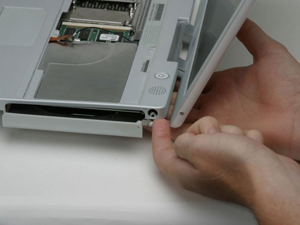
Hebe das obere Gehäuse an der linken Seite hoch und ziehe die rechte Seite heraus, damit die Buchse für die Stromversorgung frei kommt.
I had one (800MHz), that on the B&W power cable, it was so tight that it pulled the socket from the PC board. Never had that happen before, although the potential exists on many of them. Needless to say, that machine is now allocated as a parts unit. What I found is the safest way, and really not all that much trouble, is the remove the 5 screws, peel back the tape, and remove the speaker/switch units from the top cover. Worked for me, and avoided the risk mentioned above.
-
-
-
Hebe das obere Gehäuse soweit an, dass du das blaue und das weiße Versorgungskabel vom Logic Board abtrennen kannst. Heble die Stecker behutsam mit dem Fingernagel oder einem Zahnstocher aus dem Anschluss heraus. Achte darauf, dass du wirklich nur am Stecker und nicht am Anschluss hebelst.
Not unless you have to! Most parts can be removed with this left in. Don't try pulling on it unless you have to, it can easily break the logic board. Just tilt the upper case up to lean it on the display.
Much easier if you do this after Step 37.
It is alot easier to get at after you pull the speaker cable out. Use something small to pop it out of place though, I broke my extra spare being a little too hasty.
This connector has a small catch on the right. slipping a sharp object (eg: pin) between the connector and it holder will release the catch. The connector should now come off easily.
I put this comment in the last step, but perhaps it should go here as well:
I had one (800MHz), that on the B&W power cable, it was so tight that it pulled the socket from the PC board. Never had that happen before, although the potential exists on many of them. Needless to say, that machine is now allocated as a parts unit. What I found is the safest way, and really not all that much trouble, is the remove the 5 screws, peel back the tape, and remove the speaker/switch units from the top cover. Worked for me, and avoided the risk mentioned above.
-
-
-
Hebe das obere Gehäuse noch weiter hoch und trenne das rote und das schwarze Lautsprecherkabel vom Logic Board ab. Achte auch hier darauf, dass du nur am Stecker und nicht am Anschluss hebelst.
There is a magnet covering a screw to the left of the serial number located in the upper center of the upper case. Remove the magnet, smooth,round and small, and loosen (doesn't need to come out) the screw to remove the upper case. Proceed to disconnecting the speaker and power cables. NOTE: this magnet is not the same one indicated in step image 33.
Oops - second attempt to install a hard drive in this; the second time unlucky. Last time I left the red and black cable in place; this time, I ripped the socket mentioned out.
-
-
-
-
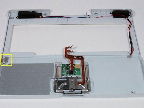
Dein Laptop sollte etwa so aussehen.
I found that at this point I was able to avoid any further steps by removing the screw from the DC in board and the flip the machine over to reveal its connection to the board. I removed this connection and then was able to wiggle the board out and snake the cord out. Avoiding Step 38 saves a lot of screw removal. Not to mention not having to remove the CD Drive also saves a lot of time.
Just be careful when doing this that you do not force the board out of its place. There is room to remove it, but it is a gentle task.
-
-
-
Entferne die folgenden vierzehn Schrauben (bei manchen Modellen sind es möglicherweise auch weniger):
-
Eine 2,5 mm Kreuzschlitzschraube
-
Sechs 3,5 mm Kreuzschlitzschrauben
-
Eine 4,5 mm Kreuzschlitzschraube mit kleinem Schaft nahe bei der Ruhezustands-LED
-
Zwei 4,5 mm Kreuzschlitzschrauben mit längerem Schaft
-
Vier 5 mm Kreuzschlitzschrauben
-
Wenn in das Loch ganz links eine Schraube eingesetzt ist, dann kann die 14,2 mm Schraube in Schritt 24, welche das obere Gehäuse nach unten drückt, nicht eingebaut werden.
Zitat von neato:
If your iBook is like mine (700MHz) The yellow screw was attached from the bottom through the bottom case and had to be removed earlier in order to remove the bottom case. Also the the green screw pictured to the left was missing already removed.
It's the same to iBook G3 600 MHz
-
-
-
Ziehe drei gelbe Klebestreifen in der unteren linken Ecke zurück.
-
Ziehe einen Folienstreifen in der oberen linken Ecke und einen anderen an der Stelle zurück, wo das Trackpad am Logic Board angeschlossen ist.
There is also foil tape, cetre front, in the cutout for the catch mechanism
-
-
-
Hebe die obere Abschirmung von der rechten Seite her an. Achte dabei da darauf, dass sich die obere linke Ecke nicht am Metallrahmen verfängt.
-


Um dein Gerät wieder zusammenbauen, folge den Schritten in umgekehrter Reihenfolge.
Um dein Gerät wieder zusammenbauen, folge den Schritten in umgekehrter Reihenfolge.
Rückgängig: Ich habe diese Anleitung nicht absolviert.
9 weitere Nutzer:innen haben diese Anleitung absolviert.
Besonderer Dank geht an diese Übersetzer:innen:
100%

Diese Übersetzer:innen helfen uns, die Welt zu reparieren! Wie kann ich mithelfen?
Hier starten ›

Also unplug the computer just before taking the two steps described above.
Ken Horner - Antwort