Diese Version enthält möglicherweise inkorrekte Änderungen. Wechsle zur letzten geprüften Version.
Was du brauchst
-
Dieser Schritt ist noch nicht übersetzt. Hilf mit, ihn zu übersetzen!
-
Lay your iBook upside down on a flat surface.
-
Use a coin to rotate the battery locking screw 90 degrees clockwise.
-
Lift the battery out of the computer.
-
-
Dieser Schritt ist noch nicht übersetzt. Hilf mit, ihn zu übersetzen!
-
Pull the keyboard release tabs toward you and lift up on the keyboard until it pops free.
-
Flip the keyboard over, away from the screen, and rest it face-down on the trackpad area.
-
-
Dieser Schritt ist noch nicht übersetzt. Hilf mit, ihn zu übersetzen!
-
Remove the four silver Phillips screws that secure the RAM shield.
-
-
Dieser Schritt ist noch nicht übersetzt. Hilf mit, ihn zu übersetzen!
-
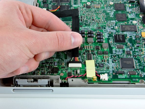
Pull the keyboard cable up from the logic board, holding the cable as close to the connector as possible.
-
-
Dieser Schritt ist noch nicht übersetzt. Hilf mit, ihn zu übersetzen!
-
Use a spudger or small flathead screwdriver to remove the three rubber feet from the lower case.
-
-
Dieser Schritt ist noch nicht übersetzt. Hilf mit, ihn zu übersetzen!
-
Remove the three newly-revealed Phillips screws.
-
-
Dieser Schritt ist noch nicht übersetzt. Hilf mit, ihn zu übersetzen!
-
Use a spudger or small flathead screwdriver to pry up the three metal rings that housed the rubber bumpers.
-
-
Dieser Schritt ist noch nicht übersetzt. Hilf mit, ihn zu übersetzen!
-
Remove the three Torx screws using a T8 Torx screwdriver.
-
-
Dieser Schritt ist noch nicht übersetzt. Hilf mit, ihn zu übersetzen!
-
Remove the two 4.5 mm Phillips screws on either sides of the battery contacts.
-
-
Dieser Schritt ist noch nicht übersetzt. Hilf mit, ihn zu übersetzen!
-
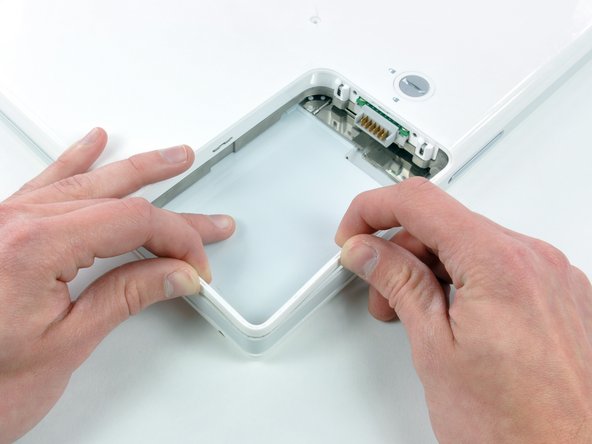
Push the thin rims of the lower case surrounding the battery compartment in, bending them past the tabs, and then lift up to free that corner of the lower case.
-
-
Dieser Schritt ist noch nicht übersetzt. Hilf mit, ihn zu übersetzen!
-
There is a slot on the wall of the battery compartment that locks the lower case in place. Use a small flathead screwdriver to pry out the slot's lower rim and pull up on the lower case to free the slot from the tabs holding it.
-
-
Dieser Schritt ist noch nicht übersetzt. Hilf mit, ihn zu übersetzen!
-
Run a spudger along the seam between the lower case and upper case on the front of the computer to free the tabs locking the lower case. Pull up on the lower case and continue to use the spudger as necessary until you hear three distinct clicks.
-
-
Dieser Schritt ist noch nicht übersetzt. Hilf mit, ihn zu übersetzen!
-
Continue to run the spudger around the front right corner. There are two tabs on the port side of the computer, one near the front corner and one near the sound-out port.
-
-
Dieser Schritt ist noch nicht übersetzt. Hilf mit, ihn zu übersetzen!
-
There are three tabs over the optical drive that must be released before the lower case can come off. Slide the spudger into the lower case above the optical drive and run it toward the back of the computer until you hear three distinct clicks.
-
-
Dieser Schritt ist noch nicht übersetzt. Hilf mit, ihn zu übersetzen!
-
Turn the computer so that the back is facing you and pull the lower case up and toward you until the back tabs pop free.
-
-
Dieser Schritt ist noch nicht übersetzt. Hilf mit, ihn zu übersetzen!
-
Remove the small greasy springs with white plastic caps from either side of the battery contacts.
-
-
Dieser Schritt ist noch nicht übersetzt. Hilf mit, ihn zu übersetzen!
-
Have patience and follow the directions, the end result is up to you.
-
-
Dieser Schritt ist noch nicht übersetzt. Hilf mit, ihn zu übersetzen!
-
Remove the following 4 screws from the bottom shield:
-
Two 3 mm Phillips.
-
Two 7.5 mm Phillips.
-
-
Dieser Schritt ist noch nicht übersetzt. Hilf mit, ihn zu übersetzen!
-
Remove the two Phillips screws securing the DC-In board, removing tape as necessary.
-
-
Dieser Schritt ist noch nicht übersetzt. Hilf mit, ihn zu übersetzen!
-
Deroute the cable from around the optical drive, removing tape as necessary.
-
Disconnect the DC-In cable from the logic board and angle the DC-In board out of its compartment.
-
-
Dieser Schritt ist noch nicht übersetzt. Hilf mit, ihn zu übersetzen!
-
Remove the two 3 mm Phillips screws inside the left edge of the battery tray.
-
Three 3 mm Phillips around the battery compartment.
-
Three 4.5 mm Phillips along the optical drive bezel. (a magnetic screwdriver may help to lift these screws out)
-
One 12 mm Phillips in the lower right corner.
-
Four 14.5 mm Phillips.
-
-
-
Dieser Schritt ist noch nicht übersetzt. Hilf mit, ihn zu übersetzen!
-
Turn over the computer and open it.
-
Use the flat side of a flathead screwdriver to remove the small magnet covering a screw near the middle of the computer.
-
-
Dieser Schritt ist noch nicht übersetzt. Hilf mit, ihn zu übersetzen!
-
Remove the following 7 screws from the edges of the keyboard area.
-
Three 2 mm Phillips along the right edge.
-
One 4.5 mm Phillips underneath where the magnet was.
-
One 6 mm Phillips with a small head in the lower left corner.
-
Two 6 mm Phillips with large heads, one in the upper left corner and one in the middle.
-
-
Dieser Schritt ist noch nicht übersetzt. Hilf mit, ihn zu übersetzen!
-
Carefully lift the upper case slightly and move it toward the front of the computer to reveal the trackpad connector. Use a spudger or your finger to disconnect the trackpad connector hidden beneath the white plastic tab.
-
After disconnecting the track pad connector, carefully rotate the upper case away from you and rest it against the display.
-
-
Dieser Schritt ist noch nicht übersetzt. Hilf mit, ihn zu übersetzen!
-
Use the sharp end of a spudger to disconnect the speaker cable connector.
-
-
Dieser Schritt ist noch nicht übersetzt. Hilf mit, ihn zu übersetzen!
-
Using the sharp end of a spudger, disconnect the connector for the blue and white power cables. Again, be careful to pry up only on the connector.
-
The upper case is now free and can be removed from the computer.
-
-
Dieser Schritt ist noch nicht übersetzt. Hilf mit, ihn zu übersetzen!
-
Remove the fifteen 3 mm Phillips screws securing the top shield to the computer.
-
Remove the following 16 screws:
-
Thirteen 3 mm Phillips.
-
One 3 mm Phillips. (actual screw not present in image)
-
Two 4 mm Phillips.
-
-
Dieser Schritt ist noch nicht übersetzt. Hilf mit, ihn zu übersetzen!
-
Lift the top shield up from the right side, minding the upper left corner, which may catch on the metal framework.
-
-
Dieser Schritt ist noch nicht übersetzt. Hilf mit, ihn zu übersetzen!
-
Disconnect the RJ-11 cable from the top of the modem.
-
-
Dieser Schritt ist noch nicht übersetzt. Hilf mit, ihn zu übersetzen!
-
Remove the two Phillips screws at the corners of the modem.
-
-
Dieser Schritt ist noch nicht übersetzt. Hilf mit, ihn zu übersetzen!
-
Lift the modem and modem shield from the bottom.
-
-
Dieser Schritt ist noch nicht übersetzt. Hilf mit, ihn zu übersetzen!
-
Remove the following three screws:
-
Two 3mm Phillips screws.
-
One 7.5 mm Phillips screw.
-
Lift the small plastic retaining bracket up and out of the computer.
-
-
Dieser Schritt ist noch nicht übersetzt. Hilf mit, ihn zu übersetzen!
-
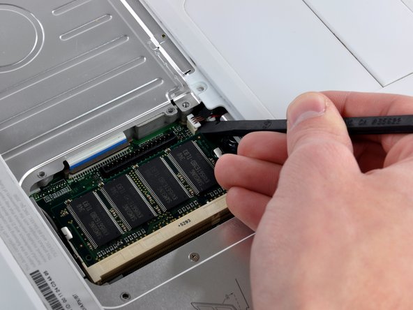
Using a spudger, pry up the AirPort/Bluetooth board from the end closest to the hard drive. Be sure to pry against the metal framework, as shown in the picture.
-
-
Dieser Schritt ist noch nicht übersetzt. Hilf mit, ihn zu übersetzen!
-
Hold the AirPort/Bluetooth board in one hand and use a spudger to disconnect the two antenna cables.
-
Remove the AirPort/Bluetooth card from the computer.
-
-
Dieser Schritt ist noch nicht übersetzt. Hilf mit, ihn zu übersetzen!
-
Turn the computer over.
-
Disconnect the inverter cable from the logic board and deroute it from the metal framework, removing tape as necessary.
-
-
Dieser Schritt ist noch nicht übersetzt. Hilf mit, ihn zu übersetzen!
-
Turn the computer back over.
-
Disconnect the microphone cable at the front of the computer, between the left side of the hard drive and the metal framework, removing tape as necessary.
-
Although not absolutely essential, removal of the hard drive will give enough space to remove the connector with your fingers.
-
-
Dieser Schritt ist noch nicht übersetzt. Hilf mit, ihn zu übersetzen!
-
Use the black plastic handle to disconnect the display data cable from the logic board by pulling straight up.
-
-
Dieser Schritt ist noch nicht übersetzt. Hilf mit, ihn zu übersetzen!
-
Peel up the yellow tape holding the display data cable to the metal framework and remove the single Phillips screw beneath it.
-
-
Dieser Schritt ist noch nicht übersetzt. Hilf mit, ihn zu übersetzen!
-
De-route the AirPort antenna cables from the heat sink.
-
-
Dieser Schritt ist noch nicht übersetzt. Hilf mit, ihn zu übersetzen!
-
Support the display with one hand and remove the single Phillips screw on either side of the hinge (two screws total).
-
-
Dieser Schritt ist noch nicht übersetzt. Hilf mit, ihn zu übersetzen!
-
Tilt the display back, freeing it from the two metal alignment posts holding the hinges in place, and lift it from the computer.
-
Display remains.
-
-
-
Entferne die beiden 1,5 mm Innensechskantschrauben auf jeder Seite des Displays (also insgesamt vier).
-
-
-
Setze das flache Ende eines Spudgers senkrecht zur Oberfläche in den Spalt zwischen der vorderen und hinteren Blende nahe bei der oberen linken Displayecke ein.
-
Kippe den Spudger vom Display weg, um die hintere von der vorderen Blende wegzuhebeln.
-
-
-
Schiebe den Spudger an der Oberkante der vorderen Displayblende entlang, um beide Blenden gleichmäßig zu trennen.
-
-
-
Schiebe das flache Ende des Spudgers von der oberen linken Ecke ausgehend nach unten und heble dabei die hintere Blende von der linken Displaykante ab.
-
-
-
Heble die hintere Blende mit dem flachen Ende des Spudgers von der rechten Seitenkante des Displays ab.
-
Heble, falls nötig, an der Unterkante der hinteren Blende, um sie vom Display abzulösen.
-
-
-
Entferne das große Stück Klebeband in der unteren rechten Displayecke.
-
-
-
Entferne die einzelne Schraube aus der Öffnung im EMI-Klebeband an der Unterkante des Displays. (Das ist die erste von zwei Schrauben an der Verschlussabdeckung)
-
Entferne mit einem Spudger die kleine Unterlegscheibe unter der eben entfernten Schraube.
-
-
-
Ziehe die Aluminium Folie/das EMI-Klebeband in einem Stück vom Aluminiumgussrahmen der Klappenscharniere.
-
-
-
Entferne das Stück Aluminiumfolie in der Mitte der LCD-Abdeckung.
-
Ziehe das Stück Klebeband ab, mit dem der Massekontakt des Displaydatenkabels an der dünnen LCD-Stahlabdeckung befestigt ist.
-
-
-
Entferne die beiden Kreuzschlitzschrauben, mit denen die Klappenscharniere des LCDs an jeder Seite befestigt sind. (Also insgesamt vier).
-
-
-
Entferne die zweite der beiden Kreuzschlitzschrauben, mit denen die Klappenabdeckung am Aluminiumgussrahmen der Klappenscharniere befestigt ist.
-
-
-
Entferne die zwei Klebebandstücke von den Displaydaten-/Mikrofonkabeln nahe der Unterkante des Displays.
-
-
-
Hebe das Mikrofon mit der Spudgerspitze aus der Frontblende heraus.
-
Fädle das Mikrofonkabel oben und seitlich am Display heraus.
-
-
-
Ziehe den Stecker am Displaydatenkabel aus seinem Anschluss auf dem LCD heraus und trenne ihn ab.
-
Entferne das Displaydatenkabel vom Display.
-
-
-
Entferne die zwei Klebebandstücke von den AirPort-/Inverterkabeln bei der Unterkante des Displays.
-
-
-
Ziehe das Kabel zur Displaybeleuchtung behutsam weg und drücke gleichzeitig den Stecker der Displaybeleuchtung mit dem flachen Ende des Spudgers aus seinem Anschluss auf dem Inverter heraus.
-
Hebe das LCD aus der Frontblende heraus und lege es zur Seite.
-
-
-
Entferne die drei Kreuzschlitzschrauben, mit denen die Platine für die Reed-Kontakte und die AirPort-Antenne an der Frontblende befestigt sind.
-
Fädle die Inverter-/Mikrofonkabel seitlich am Display heraus.
-
-
-
Löse behutsam den Massekontakt des Inverterkabels vom Aluminiumgussrahmen der Scharniere ab.
-
Ziehe das Inverterkabel weg von seinem Anschluss auf der Inverterplatine und hole gleichzeitig mit der Spudgerspitze seinen Stecker aus dem Anschluss heraus.
-
-
-
Entferne die beiden Kreuzschlitzschrauben, mit denen die AirPort-Antenne an der Frontblende befestigt ist.
-
Fädle das AirPort-Antennenkabel aus der Displaykante heraus.
-
-
-
Wenn du das 1,33 GHz 12 Zoll G4 iBook hast, entferne einfach die AirPort-/ Inverterkabel.
-
Bei allen anderen Modellen musst du erst die Antennenplatine mit dem flachen Ende des Spudgers von der Frontblende entfernen.
-
Entferne die AirPort-/Inverterkabel.
-


Rückgängig: Ich habe diese Anleitung nicht absolviert.
2 weitere Nutzer:innen haben diese Anleitung absolviert.
