Diese Version enthält möglicherweise inkorrekte Änderungen. Wechsle zur letzten geprüften Version.
Was du brauchst
-
-
Löse die beiden unverlierbaren Kreuzschlitzschrauben, mit deinen die Zugangsklappe am iMac befestigt ist..
-
Entferne die Zugangsklappe zum iMac.
-
-
-
Entferne die folgenden vier Schrauben:
-
Drei 6 mm T8 Torx.
-
Eine 8 mm T8 Torx.
-
-
-
Drehe den iMac um und lege ihn mit der Standseite nach unten auf eine ebene Fläche.
-
Um die vordere Blende vom iMac abzuheben, führe die folgenden Schritte gleichzeitig durch:
-
Verwende deinen Daumen, um die RAM-Arme einzudrücken und den iMac festzuhalten.
-
Benutze deinen Zeigefinger, um die kleine Brücke an der vorderen Blende zu dir hin zu ziehen.
-
Hebe die vordere Blende mit den Zeigefingern an.
-
Sobald die kleine Materialbrücke die RAM-Arme passiert hat, hebe die vordere Blende an ihrer unteren Kante gerade genug an, um die untere Kante des hinteren Gehäuses zu überwinden.
-
-
-
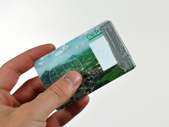
Führe eine Plastikkarte in die Ecke des Belüftungsschlitzes in der Nähe der Oberseite des hinteren Gehäuses ein.
-
Schiebe die Karte in Richtung Oberseite des iMacs, um die Verriegelung der Frontblende zu lösen.
-
Ziehe die Frontblende vom restlichen Gehäuse weg.
-
Wiederhole diesen Vorgang für die andere Seite der Frontblende.
-
Sollte sich die Blende nicht lösen lassen, drücke die untere Kante wieder auf das hintere Gehäuse und wiederhole den Vorgang mit der Plastikkarte.
-
-
-
Lege deinen iMac mit der Standfläche nach unten auf einen Tisch.
-
Hebe die Frontblende von der unteren Kante an und drehe die Blende vom Rest des iMac weg, wobei du auf die RAM-Hebel achten mußt, die sich verfangen könnten.
-
Lege die Frontblende über den Rest des iMac.
-
-
-
Wenn nötig, entferne das gelbe Kapton Klebeband (es ist ok es dann wegzuwerfen), welches um die Mikrofon- und Kamerakabel gewickelt ist.
-
-
Dieser Schritt ist noch nicht übersetzt. Hilf mit, ihn zu übersetzen!
-
Peel up the lower EMI shield from the rear case.
-
-
-
Dieser Schritt ist noch nicht übersetzt. Hilf mit, ihn zu übersetzen!
-
Remove the two 4.8 mm T6 Torx screws securing the display data cable to the logic board.
-
Grab the display data cable connector by its black tab and pull it straight up off the logic board.
-
-
Dieser Schritt ist noch nicht übersetzt. Hilf mit, ihn zu übersetzen!
-
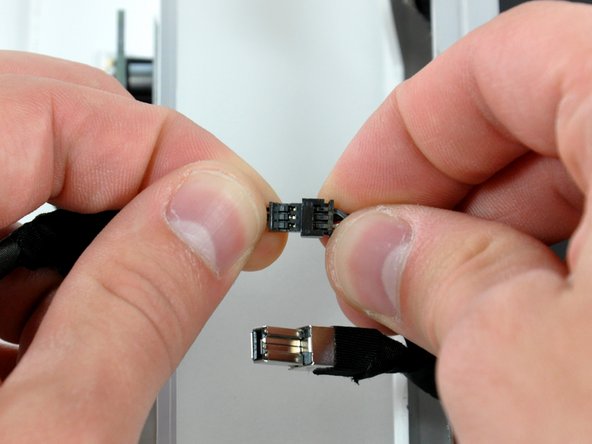
Inverter cable on 24inch iMac pulls off to the left.
-
Pull the inverter cable connector straight up off its socket on the logic board.
-
-
Dieser Schritt ist noch nicht übersetzt. Hilf mit, ihn zu übersetzen!
-
Peel back the aluminum EMI tape from the two vertical edges of the display.
-
-
Dieser Schritt ist noch nicht übersetzt. Hilf mit, ihn zu übersetzen!
-
Remove the four 8 mm with 2 mm thick head coarse-thread T10 Torx screws securing the display to the rear case.
-
-
Dieser Schritt ist noch nicht übersetzt. Hilf mit, ihn zu übersetzen!
-
Lift the display from its lower edge and pull it toward yourself to peel off the EMI shield attached to its top edge.
-
-
Dieser Schritt ist noch nicht übersetzt. Hilf mit, ihn zu übersetzen!
-
What you will need to complete this install:
-
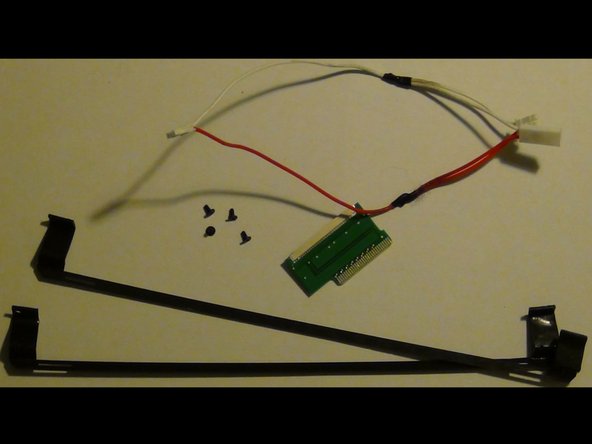
Contents of UniMac V4 Adapter Kit:
-
UniMac V4 Adapter
-
Mounting brackets
-
CCFL Adapter
-
Phillips Screws
-
Required tools listed prior, compatible LCD panel, insulation tape (clear packing tape works well)
-
-
Dieser Schritt ist noch nicht übersetzt. Hilf mit, ihn zu übersetzen!
-
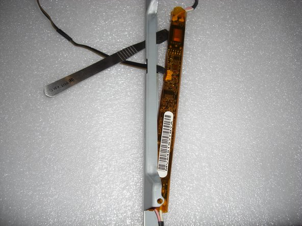
Remove both metal brackets from the original LCD screen.
-
Remove 2 torx screws from each side. Each bracket should then be easily removed.
-
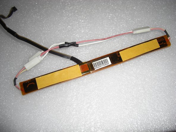
Remove the LCD inverter from the metal bracket. It is held in with some light adhesive.
-
-
Dieser Schritt ist noch nicht übersetzt. Hilf mit, ihn zu übersetzen!
-
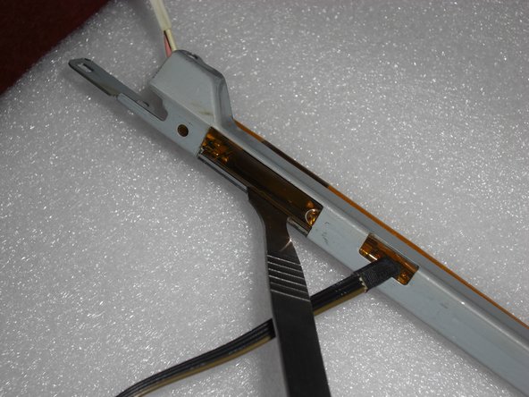
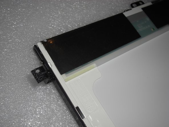
Attach the included plastic adapters to the replacement LCD screen.
-
The adapter with the larger leg space has to be mounted on the "right" side of the LCD. That's where the LVDS connector is located.
-
The brackets screw directly to the screen using the included phillips screws.
-
-
Dieser Schritt ist noch nicht übersetzt. Hilf mit, ihn zu übersetzen!
-
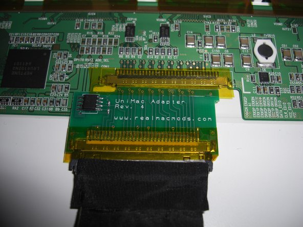
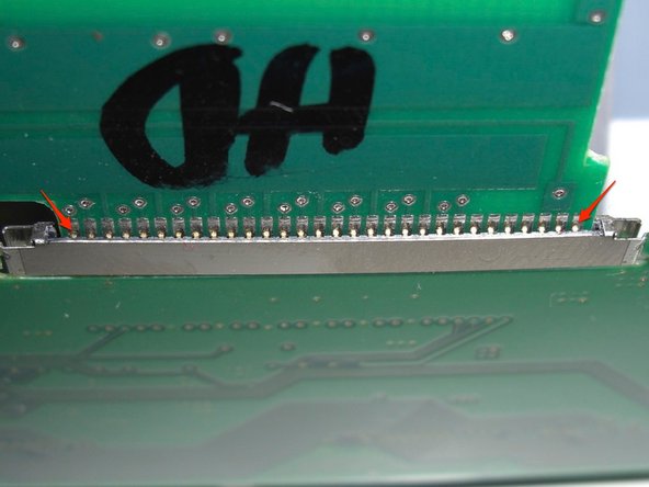
Attach the UniMac V4 Adapter to the LCD screen.
-
Simply clip it into the LVDS socket.
-
Ensure a solid connection and then put a piece of packing tape over the adapter.
-
Attach the LVDS cable, that you removed earlier, to the UniMac V4 Adapter. Ensure a solid connection and put a piece of packing tape over it.
-
-
Dieser Schritt ist noch nicht übersetzt. Hilf mit, ihn zu übersetzen!
-
Attach the included CCFL adapter to the original inverter board.
-
Apply some self adhesive tape at the bottom of the board.
-
-
Dieser Schritt ist noch nicht übersetzt. Hilf mit, ihn zu übersetzen!
-
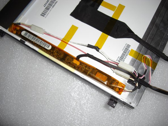
Fix the LVDS cable with some adhesive tape. This reduces mechanical force applied to the UniMac Adapter and makes the modification more stable.
-
Now place the inverter board at the left side of the LCD. There's enough room between the CD-ROM drive and the LCD, so there's the optimal place.
-
You should now have a fully assembled display ready for install.
-
-
Dieser Schritt ist noch nicht übersetzt. Hilf mit, ihn zu übersetzen!
-
Vertical alignment:
-
Each bracket utilizes 2 screws mounted through 2 slots. This allows a few inches of movement up or down.
-
You will likely need to go back and make adjustments after the install.
-
Just loosen the 2 screws and slide the bracket up or down as needed and then tighten screws.
-
-
Dieser Schritt ist noch nicht übersetzt. Hilf mit, ihn zu übersetzen!
-
Mounting screen:
-
Mount the screen using the original torx screws used the mount the OEM panel.
-
Plug the LVDS cable into the logic board.
-
-
Dieser Schritt ist noch nicht übersetzt. Hilf mit, ihn zu übersetzen!
-
Reassembly and test:
-
Double check everything and once you are confident everything went well, install the front bezel.
-
Attach the power cable, and hit the power button.
-
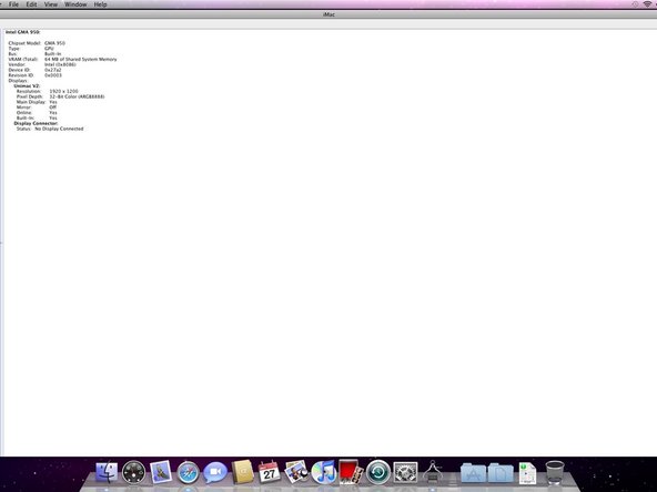
You should now be greeted by a white screen and the Apple logo.
-
It should now be apparent if any alignment adjustments need to be made.
-
-
Dieser Schritt ist noch nicht übersetzt. Hilf mit, ihn zu übersetzen!
-
Trouble:
-
Should you have any install issues please contact Adam@realmacmods.com for assistance.
-


Rückgängig: Ich habe diese Anleitung nicht absolviert.
5 weitere Nutzer:innen haben diese Anleitung absolviert.
2 Kommentare
My replacement screen has two wired out puts to put into the ccfl adaptor. The screen is one known to work.
Is correct?