Diese Version enthält möglicherweise inkorrekte Änderungen. Wechsle zur letzten geprüften Version.
Was du brauchst
-
-
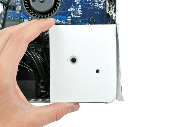
Löse die beiden Kreuzschlitzschrauben, mit denen die Zugangsklappe an deinem iMac befestigt ist.
-
Entferne die Zugangsklappe.
-
-
Dieser Schritt ist noch nicht übersetzt. Hilf mit, ihn zu übersetzen!
-
Remove the following screws along the lower edge of your iMac:
-
Three 6 mm T8 Torx screws
-
One 8 mm T8 Torx screw (Right side of the RAM slot on 2105)
-
-
Dieser Schritt ist noch nicht übersetzt. Hilf mit, ihn zu übersetzen!
-
Insert a plastic card up into the corner of the air vent slot near the top of the rear case.
-
Push the card toward the top of the iMac to release the front bezel latch.
-
Pull the front bezel away from the rear case.
-
Repeat this process for the other side of the front bezel.
-
If the bezel refuses to release, try lifting the lower edge of the front bezel slightly away from the rear case (detailed in the next few steps) and repeat the latch release process.
-
-
Dieser Schritt ist noch nicht übersetzt. Hilf mit, ihn zu übersetzen!
-
Lay your iMac stand-side down on a flat surface.
-
To lift the front bezel off the iMac, simultaneously:
-
Use your thumbs to press in the RAM arms and hold the iMac down.
-
Use your index fingers to pull the small bridge of material on the front bezel toward yourself.
-
Pull the front bezel up with your index fingers.
-
Once the small bridge of material has cleared the RAM arms, lift the front bezel by its lower edge just enough to clear the bottom edge of the rear case.
-
-
Dieser Schritt ist noch nicht übersetzt. Hilf mit, ihn zu übersetzen!
-
Lift the front bezel off the rear case and rotate it away from the bottom edge of the iMac, minding the camera and microphone cables still attached to its upper edge.
-
-
Dieser Schritt ist noch nicht übersetzt. Hilf mit, ihn zu übersetzen!
-
Disconnect the microphone cable.
-
Disconnect the camera cable by pulling its connector away from the socket on the camera board.
-
-
Dieser Schritt ist noch nicht übersetzt. Hilf mit, ihn zu übersetzen!
-
Peel up the lower EMI shield from the rear case.
-
-
Dieser Schritt ist noch nicht übersetzt. Hilf mit, ihn zu übersetzen!
-
Tape the EMI shield to the face of the display to keep it out of the way.
-
-
Dieser Schritt ist noch nicht übersetzt. Hilf mit, ihn zu übersetzen!
-
Remove the two 5 mm T6 Torx screws securing the display data cable connector to the logic board.
-
Pull the display data cable connector up off the logic board by its black pull tab.
-
-
Dieser Schritt ist noch nicht übersetzt. Hilf mit, ihn zu übersetzen!
-
Peel back the EMI tape from the two vertical edges of the display.
-
-
Dieser Schritt ist noch nicht übersetzt. Hilf mit, ihn zu übersetzen!
-
Allow the lower EMI shield to hang down from the display.
-
Remove the four 7.5 mm T10 Torx screws securing the display to the rear case.
-
-
Dieser Schritt ist noch nicht übersetzt. Hilf mit, ihn zu übersetzen!
-
Lift the lower edge of the display and rotate it toward the top edge of your iMac.
-
-
-
Dieser Schritt ist noch nicht übersetzt. Hilf mit, ihn zu übersetzen!
-
Disconnect both inverter cables from the inverter board.
-
-
Dieser Schritt ist noch nicht übersetzt. Hilf mit, ihn zu übersetzen!
-
Disconnect the two inverter cables at the top edge of the inverter using the method explained in the previous step.
-
-
Dieser Schritt ist noch nicht übersetzt. Hilf mit, ihn zu übersetzen!
-
Rotate the display until it is nearly perpendicular to the rear case and lift it up to peel it off the EMI shield stuck to its top edge.
-
-
Dieser Schritt ist noch nicht übersetzt. Hilf mit, ihn zu übersetzen!
-
Remove the single T10 Torx screw securing the left speaker to the rear case.
-
Pull the left speaker out of the rear case.
-
-
Dieser Schritt ist noch nicht übersetzt. Hilf mit, ihn zu übersetzen!
-
Use the flat end of a spudger to pry both antenna connectors up off the AirPort Extreme card.
-
-
Dieser Schritt ist noch nicht übersetzt. Hilf mit, ihn zu übersetzen!
-
Use a metal spudger to disconnect the SATA data cable up off the logic board.
-
-
Dieser Schritt ist noch nicht übersetzt. Hilf mit, ihn zu übersetzen!
-
Pull the IR board cable connector away from its socket on the IR board.
-
-
Dieser Schritt ist noch nicht übersetzt. Hilf mit, ihn zu übersetzen!
-
De-route the speaker cables from beneath the IR Board and heatsink assembly.
-
-
Dieser Schritt ist noch nicht übersetzt. Hilf mit, ihn zu übersetzen!
-
Remove the single T10 Torx screw securing the right speaker to the logic board.
-
Lift the right speaker out of the rear case and move it out of the way.
-
-
Dieser Schritt ist noch nicht übersetzt. Hilf mit, ihn zu übersetzen!
-
Disconnect the speaker cable connector by lifting it straight up off its socket on the logic board.
-
-
Dieser Schritt ist noch nicht übersetzt. Hilf mit, ihn zu übersetzen!
-
Disconnect the HDD fan and power button from the logic board by pulling their connectors straight up off the sockets on the logic board.
-
-
Dieser Schritt ist noch nicht übersetzt. Hilf mit, ihn zu übersetzen!
-
If necessary, remove the pieces of tape holding the SATA data cable to the logic board.
-
Move the SATA data cable away from the face of the logic board.
-
-
Dieser Schritt ist noch nicht übersetzt. Hilf mit, ihn zu übersetzen!
-
Disconnect the DC-In cable by simultaneously depressing both locking arms and pulling its connector away from the socket on the logic board toward the top of your iMac.
-
-
Dieser Schritt ist noch nicht übersetzt. Hilf mit, ihn zu übersetzen!
-
Pull the ambient light sensor cable connector up off the logic board.
-
-
Dieser Schritt ist noch nicht übersetzt. Hilf mit, ihn zu übersetzen!
-
Use the flat end of a spudger to pry the Bluetooth antenna cable connector up off the Bluetooth board.
-
-
Dieser Schritt ist noch nicht übersetzt. Hilf mit, ihn zu übersetzen!
-
Carefully de-route the IR board cable out from under the IR board and move it out of the way of the logic board.
-
-
Dieser Schritt ist noch nicht übersetzt. Hilf mit, ihn zu übersetzen!
-
Disconnect the following connectors from the logic board:
-
Camera/IR board cable.
-
Optical drive fan.
-
-
Dieser Schritt ist noch nicht übersetzt. Hilf mit, ihn zu übersetzen!
-
Disconnect the optical drive thermal sensor cable from the logic board by pulling its connector away from the socket on the logic board.
-
-
Dieser Schritt ist noch nicht übersetzt. Hilf mit, ihn zu übersetzen!
-
Remove the two T6 Torx screws securing the optical drive ribbon cable connector to the logic board.
-
-
Dieser Schritt ist noch nicht übersetzt. Hilf mit, ihn zu übersetzen!
-
Use the flat end of a spudger to pry the optical drive ribbon cable connector up off the logic board.
-
Bend the optical drive ribbon cable back away from the logic board.
-
-
Dieser Schritt ist noch nicht übersetzt. Hilf mit, ihn zu übersetzen!
-
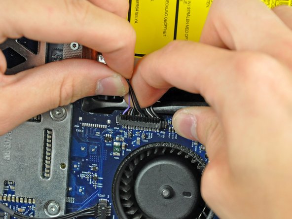
Disconnect the following connectors from the logic board:
-
Hard drive thermal sensor cable.
-
CPU fan cable.
-
-
Dieser Schritt ist noch nicht übersetzt. Hilf mit, ihn zu übersetzen!
-
Remove the two T6 Torx screws securing the top of the heat sink framework to the chassis.
-
-
Dieser Schritt ist noch nicht übersetzt. Hilf mit, ihn zu übersetzen!
-
Remove the following seven screws securing the logic board to the rear case:
-
Three coarse-thread T10 Torx.
-
Three fine-thread T10 Torx.
-
One long coarse-thread T10 Torx.
-
-
Dieser Schritt ist noch nicht übersetzt. Hilf mit, ihn zu übersetzen!
-
Carefully rotate the top edge of the logic board out of the rear case and lift the board up out of the iMac, minding the RAM arms and any cables that may get caught.
-


Rückgängig: Ich habe diese Anleitung nicht absolviert.
38 weitere Nutzer:innen haben diese Anleitung absolviert.

Ein Kommentar
Dear Walter Galan,After disassembling my Apple IMac,I happened to see your guide.Ofcourse very interesting.Now I want your expert tips to solve my problem.When I switched on the device,I got only vertical color lines on the display.No apple symbol or letters,but initial sound was there.Kindly let me know the exact problem and how to solve.If you mail me the circuit diagram of the motherboard,it would be very usefull to me.Also reference voltages at various stages. My mail id : saswra@gmail.com.
Thanking you
Ramachandran