Zum Hauptinhalt wechseln

Diese Version enthält möglicherweise inkorrekte Änderungen. Wechsle zur letzten geprüften Version.

Was du brauchst

  1. , Schutzblech: Schritt 1, Bild 1 von 1
    • Löse die Kreuzschlitzschraube in der Mitte des Schutzblechs.

    • Diese Schraube lässt sich nicht komplett vom Blech entfernen.

    • Entferne das Schutzblech vom iMac.

  2. , Glasscheibe: Schritt 2, Bild 1 von 2 , Glasscheibe: Schritt 2, Bild 2 von 2
    In diesem Schritt verwendetes Werkzeug:
    Heavy-Duty Suction Cups (Pair)
    $14.95
    Kaufen
    • Die Glasscheibe ist auf der Frontblende mit insgesamt 14 Magneten befestigt.

    • Setze zwei Saugheber auf gegenüberliegende Ecken der Glasscheibe.

    • Zum Anbringen der von uns verkauften Saugheber positioniere zunächst den beweglichen Teil des Griffs parallel zur Glasfläche. Drücke den Griff dann leicht gegen das Glas und hebe den beweglichen Teil des Saughebers, bis er parallel zu dem anderen Griffteil ist.

    • Wenn die Saugheber nicht haften, reinige sowohl die Glasscheibe als auch die Heber mit einer milden Seifenlauge.

  3. : Schritt 3, Bild 1 von 1
    • Ziehe die Glasscheibe gerade nach oben vom iMac ab.

    • Die Glasscheibe verfügt auf ihrem Umfang über mehrere Positionierstifte. Um ein Abbrechen der Stifte zu vermeiden achte bei der Demontage darauf, die Glasscheibe wirklich senkrecht nach oben zu ziehen.

    • Reinige beim Wiedereinbau das LCD und die Innenseite der Glasscheibe sehr sorgfältig, da sonst ggf. Staub und Fingerabdrücke verbleiben, die störend sichtbar werden, wenn das LCD eingeschaltet wird. Es empfiehlt sich, die Glasscheibe beim Ausbau mit der Innenseite auf einer frischen Aluminiumfolie zu platzieren, um Verschmutzungen zu vermeiden.

  4. , Frontblende: Schritt 4, Bild 1 von 1
    • Entferne die folgenden 12 Schrauben, welche die Frontblende am dahinter liegenden Gehäuse befestigen:

    • Acht 13 mm T8 Torx.

    • Vier 25 mm T8 Torx.

  5. : Schritt 5, Bild 1 von 1
    • Lege deine Hände auf die oberen Ecken der Blende (an der Seite) und hebe die Blende 2-3 cm oben vom Gehäuse ab. Danach kannst du die Blende auch unten aushängen (Die Speichermodule haben verhindert, dass du die Blende zuerst unten abnehmen kannst). Beim Zusammenbau musst du unten anfangen.

    • Im oberen Rand der Blende befindet sich ein an das Logic Board angeschlossenes Mikrofon. Hebe die Blende behutsam an, damit das Mikrofonkabel und der Stecker nicht versehentlich beschädigt werden.

    • Jetzt kannst du entweder das Mikrofonkabel abtrennen und die Blende entfernen, oder du kannst das Mikrofonkabel angeschlossen lassen und die Blende auf dem Arbeitstisch oder das Gehäuse des iMac legen.

    • Zum Entfernen der Blende musst du den Mikrofonstecker ablösen, wenn nötig das Klebeband abziehen.

    • Wenn das Mikrofonkabel angeschlossen bleiben soll, dann lasse es mit dem Logic Board verbunden und lege die Blende auf das Gehäuse drauf, wobei das Mikrofonkabel wie ein Gelenk geformt wird.

    • Wenn du das Mikrofon am Gehäuse angeschlossen lässt, dann achte darauf nicht gegen die lose Blende zu stoßen, sonst könnte das das Mikrofon oder die Hauptplatine versehentlich beschädigt werden.

  6. : Schritt 6, Bild 1 von 2 : Schritt 6, Bild 2 von 2
    • Beim Zusammenbau der Frontblende:

    • Schiebe das Kabel und den Stecker des Mikrofons vorsichtig in die Öffnung neben dem Kameraboard.

    • Ziehe den Stecker vorsichtig durch die Öffnung im Rahmen rechts neben der iSight Kamera. Schiebe den Stecker nach der Montage des Rahmens wieder durch die Öffnung zurück.

  7. , Bildschirm: Schritt 7, Bild 1 von 2 , Bildschirm: Schritt 7, Bild 2 von 2
    • Ziehen Sie den Stecker des LCD-Temperatursensors gerade nach oben aus dem Sockel auf der Hauptplatine.

    • Ziehe dabei falls erforderlich das Kabel des Sensors hinter der Hauptplatine hervor.

    • Überprüfe beim Ausbau des LCD die Kabelführung des Sensors. Achte darauf, dass das Kabel beim Wiedereinbau des Bildschirms nicht eine der Schrauben für die Frontblende blockiert.

  8. : Schritt 8, Bild 1 von 1
    • Entferne die zwei 5,3 mm Torx T6 Schrauben, welche das Bildschirmkabel an der Hauptplatine befestigen.

  9. : Schritt 9, Bild 1 von 1
    • Nutze die schwarze Ziehlasche, um das Bildschirmkabel von der Hauptplatine abzuziehen.

  10. : Schritt 10, Bild 1 von 2 : Schritt 10, Bild 2 von 2
    • Entferne die acht 12 mm Torx T8 Schrauben, welche den Bildschirm am hinteren Gehäuse befestigen.

    • Unter Umständen passt ein Torx T9 Schraubendreher besser.

    • Hebe den Bildschirm von seiner linken Kante her an und drehe ihn in Richtung der rechten Seite des iMac.

  11. : Schritt 11, Bild 1 von 2 : Schritt 11, Bild 2 von 2
    • Entferne bei angehobenem Bildschirm die vier Stromkabel.

    • Lege beim Zusammenbau die vier Stromkabelanschlüsse in Hohlräume zwischen den Komponenten an der Rückseite, so dass der Bildschirm bündig aufliegt.

    • Beim Zusammenbau ist die Reihenfolge der Stromkabel innerhalb eines Anschlusses austauschbar.

    • Sollte beim Austausch der Festplatte eine weitere Person helfen, so ist es (nach Lösung des Temperatursensors und des Bildschirmkabels im vorherigen Schritt) möglich, den Austausch bei angehobenem Display vorzunehmen.

  12. Dieser Schritt ist noch nicht übersetzt. Hilf mit, ihn zu übersetzen!

    : Schritt 12, Bild 1 von 3 : Schritt 12, Bild 2 von 3 : Schritt 12, Bild 3 von 3
    • The rest of this procedure should be done in the cleanest possible work environment to avoid dust getting BEHIND the LCD (I learned this the HARD way!)

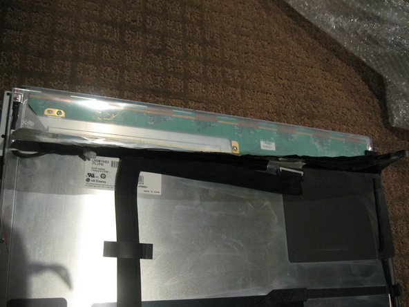
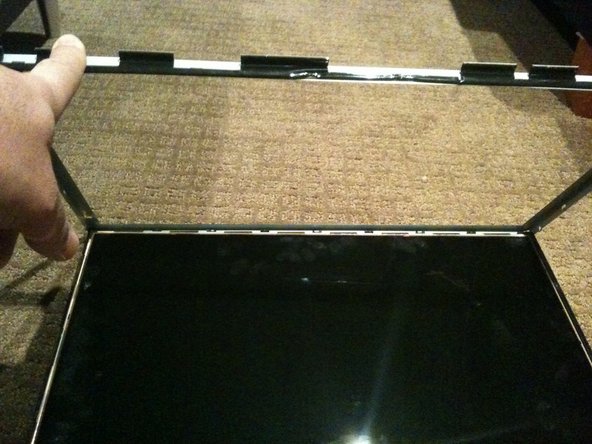
    • Once the LCD panel is removed you need to peel back the black foil from the top edge of the LCD to reveal the clear plastic PCB protector.

    • Now gently peel the clear plastic PCB protector off the top edge. Make sure you don't damage the flex cables attached to the PBC you are exposing.

    • There are a total of 8 flex cables along the top edge

  13. Dieser Schritt ist noch nicht übersetzt. Hilf mit, ihn zu übersetzen!

    : Schritt 13, Bild 1 von 3 : Schritt 13, Bild 2 von 3 : Schritt 13, Bild 3 von 3
    • Use a sharpie or similar, mark the side brackets on either side of the LCD panel before removing screws as they are different

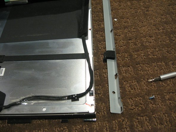
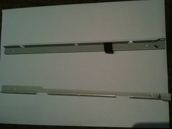
    • Use a T10 Torx driver to remove the 2 screws from each side bracket (total 4 screws)

  14. Dieser Schritt ist noch nicht übersetzt. Hilf mit, ihn zu übersetzen!

    : Schritt 14, Bild 1 von 3 : Schritt 14, Bild 2 von 3 : Schritt 14, Bild 3 von 3
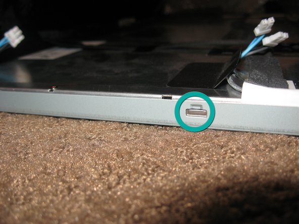
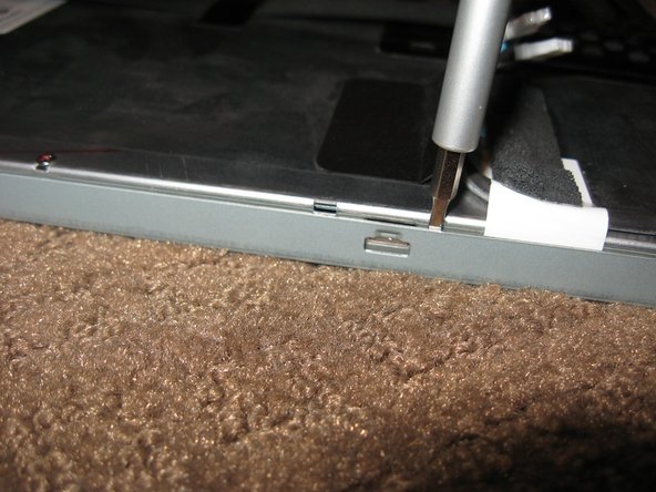
    • Stand the LCD panel on its TOP edge and locate the lock tabs along the BOTTOM edge. There are 5 along the length of the bottom edge

    • Use a flat blade driver or metal spudger to Gently pop the bezel off the lock tabs.

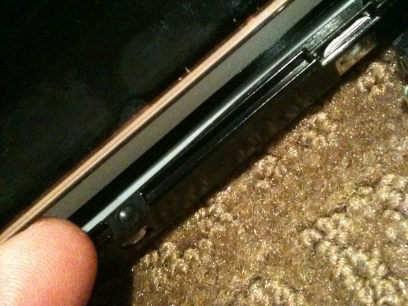
    • Locate the lock tabs on either side of the LCD panel. There are 2 on each side

    • Use a flat blade driver or metal spudger to Gently pop the bezel off the side lock tabs.

  15. Dieser Schritt ist noch nicht übersetzt. Hilf mit, ihn zu übersetzen!

    : Schritt 15, Bild 1 von 3 : Schritt 15, Bild 2 von 3 : Schritt 15, Bild 3 von 3
    • Now gently separate the metal bezel from the main body of the LCD panel

    • Lay the LCD panel down on with viewing side UP and remove the metal bezel

    • Make sure you are careful when removing the bezel from the TOP edge as you will be exposing the 8 flex cables mentioned in step 1.

    • Note the 3 flex tabs on the left edge

    • Do not damage any of the tabs or flex cables as these are the Row and Column Drivers. Damage to these will will cause faults like vertical/horizontal lines or white screen etc.

    • WARNING - Once the bezel is removed the LCD is LOOSE in the black plastic frame - only held in by the small gasket underneath.

  16. Dieser Schritt ist noch nicht übersetzt. Hilf mit, ihn zu übersetzen!

    : Schritt 16, Bild 1 von 2 : Schritt 16, Bild 2 von 2
    • Using a plastic spudger or pry tool, work GENTLY around the edges of the LCD to loosen it from the gasket below - use GREAT CARE so you don't crack or chip the panel as it is only a couple mm thick

    • Once the LCD is loose you need to HOLD it in place in the black plastic frame and GENTLY flip the entire assembly so the LCD is flat on the work surface

  17. Dieser Schritt ist noch nicht übersetzt. Hilf mit, ihn zu übersetzen!

    : Schritt 17, Bild 1 von 2 : Schritt 17, Bild 2 von 2
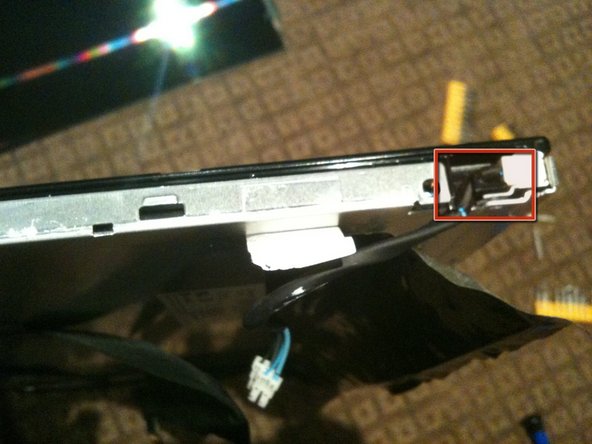
    • Remove the tape securing the LVDS cable

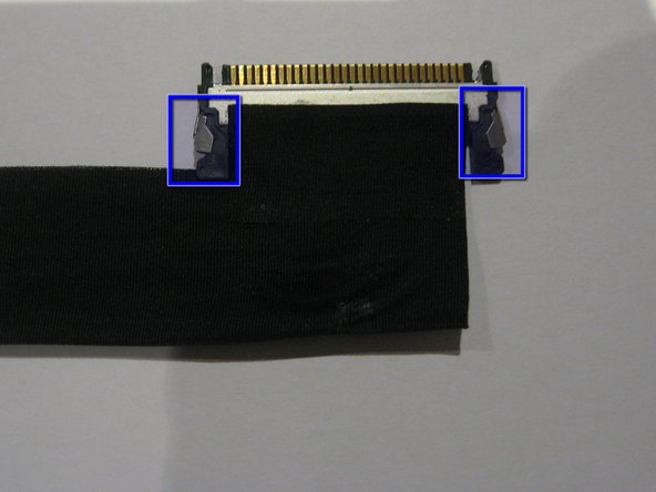
    • Press IN the 2 silver spring loaded catches on either side to release the cable and gently extract it from the connector

  18. Dieser Schritt ist noch nicht übersetzt. Hilf mit, ihn zu übersetzen!

    : Schritt 18, Bild 1 von 2 : Schritt 18, Bild 2 von 2
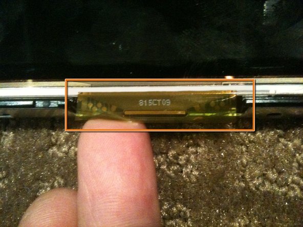
    • Peel the back Black foil and clear plastic PCB protector to fully expose the PCB that runs across the top of the LCD assembly

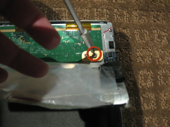
    • Remove the 2ea Philips head screws from each end of the PCB

    • The PCB actually has a 3rd screw hole in the centre of the board. Perhaps my assembly is missing a screw

  19. Dieser Schritt ist noch nicht übersetzt. Hilf mit, ihn zu übersetzen!

    : Schritt 19, Bild 1 von 2 : Schritt 19, Bild 2 von 2
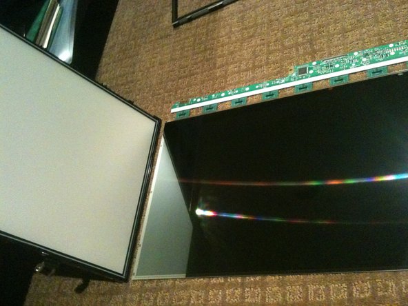
    • Gently flip the PCB over 180deg so it is off the aluminum back panel.

    • Be CAREFUL not to damage the 8 flex cables

    • The PCB may be attached to the aluminium by some adhesive near the LVDS connector. IF so use a plastic pry tool or spudger to GENTLY lift the PCB up

    • Now lift the the back panel off the LCD separating the LCD from the back light assembly

  20. Dieser Schritt ist noch nicht übersetzt. Hilf mit, ihn zu übersetzen!

    : Schritt 20, Bild 1 von 3 : Schritt 20, Bild 2 von 3 : Schritt 20, Bild 3 von 3
    • Disassembling the back-light assembly is a little fiddly as there are a number of parts that all want to come apart at the same time

    • Remove the 6 Philips screws from the rear of the back light assembly

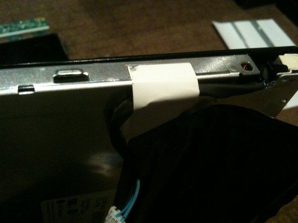
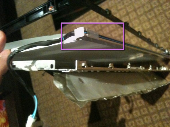
    • Removing the white tape from the CCFL cable.

    • Un-clip the CCFL cable from the black plastic surround

    • There are 2 CCFL cables and the process is essentially the same for each

  21. Dieser Schritt ist noch nicht übersetzt. Hilf mit, ihn zu übersetzen!

    : Schritt 21, Bild 1 von 3 : Schritt 21, Bild 2 von 3 : Schritt 21, Bild 3 von 3
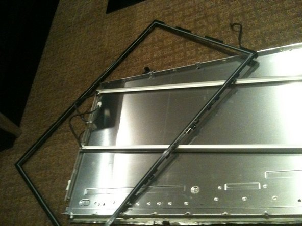
    • Separate the black plastic surround from the aluminum back plate to access the CCFL tube assemblies

    • Start by un-clipping the tabs along the top edge of the assembly. There are 4 tabs along the top

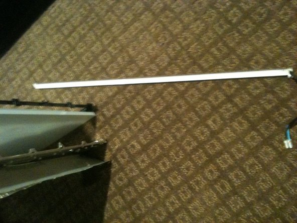
    • The top CCFL tube can be seen and CAREFULLY removed

  22. Dieser Schritt ist noch nicht übersetzt. Hilf mit, ihn zu übersetzen!

    : Schritt 22, Bild 1 von 3 : Schritt 22, Bild 2 von 3 : Schritt 22, Bild 3 von 3
    • The bottom of the black surround can now be un-clipped and the entire surround removed

    • There are 4 tabs along the bottom of the assembly

    • Once the black surround is off the rest pretty much comes apart with the bottom CCFL tube being able to be removed in a similar manner to the top

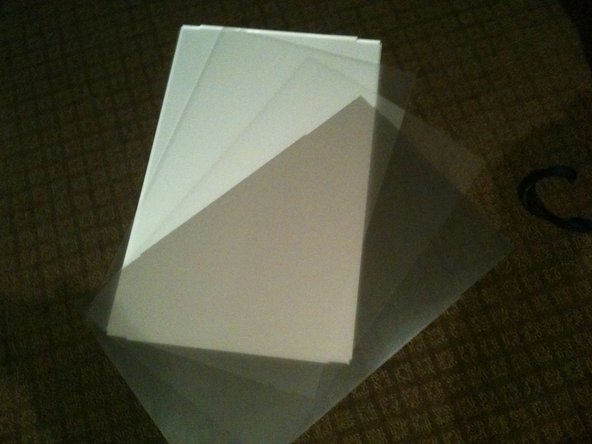
    • The centre of the back light assembly is made up of 4 main parts. A perspex sheet with white plastic coating, 2 opaque matt plastic sheets, and 1 Pearlescent matt plastic sheet

    • The plastic sheets are polarisers so need to be kept clean and free of dust and scratches

  23. Dieser Schritt ist noch nicht übersetzt. Hilf mit, ihn zu übersetzen!

    : Schritt 23, Bild 1 von 3 : Schritt 23, Bild 2 von 3 : Schritt 23, Bild 3 von 3
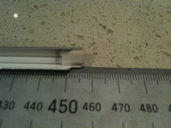
    • The CCLF tube assemblies are made up of a U shaped reflector with 2ea individual tubes inside. The entire assembly is 457mm long and 7.6mm wide. There are no part numbers on the assembly however there is a S on the end with the wires attached and an 18 on the other end.

    • The 2 CCFL tubes are held together with a figure 8 rubber band in the middle of the reflector so both tubes must come out at the same time.

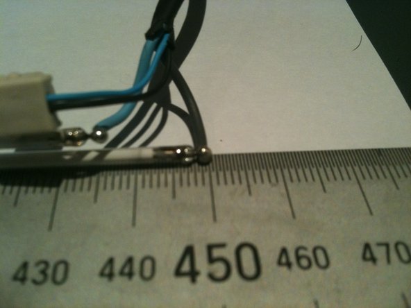
    • The individual tubes are 448mm long (excluding the terminals - standard way to measure is end of glass to end of glass) and are 2.4mm diameter.

    • The CCFL are soldered to the wires so not a simple plug in replacement

    • The CCFL are EXTREMELY fragile so ensure you dont break them when installing them.

    • The CCFL reflectors are a tight fit over the sides of the perspex sheet and the other layers of plastic. Patience and a plastic spudger or pry tool should get you there

    • The closest I can find to my CCFL measurements are either the 446mm x 2.4mm or the 450mm x 2.4mm so I'd suggest the 446mm is used

    • See the Removing CCFL from iMac 20in LCD CCFL assembly guide for details

Ziellinie

6 weitere Nutzer:innen haben diese Anleitung absolviert.

Richdave

Mitglied seit: 04/09/10

32.051 Reputation

30 Anleitungen geschrieben

Team

Master Techs Mitglied von Master Techs

Community

322 Mitglieder

2.521 Anleitungen geschrieben

2 Kommentare

I'm trying to find some information on replacing the power supply temperature sensor cable. Mine broke during removal of a bad power supply. Me too.

Yoki - Antwort

This tutorial is wrong, you don´t need to take apart the lcd, only the metal frame and the screws for each backlight, it then easily slides out.

cassio - Antwort

Kommentar hinzufügen

Seitenaufrufe:

Letzte 24 Stunden: 4

Letzte 7 Tage: 11

Letzte 30 Tage: 28

Insgesamt: 26,746