Diese Version enthält möglicherweise inkorrekte Änderungen. Wechsle zur letzten geprüften Version.
Was du brauchst
-
-
Löse die Kreuzschlitzschraube in der Mitte des Schutzblechs.
-
Entferne das Schutzblech vom iMac.
-
-
-
Setze zwei Saugheber auf gegenüberliegende Ecken der Glasscheibe.
-
-
-
-
Entferne die folgenden 12 Schrauben, welche die Frontblende am dahinter liegenden Gehäuse befestigen:
-
Acht 13 mm T8 Torx.
-
Vier 25 mm T8 Torx.
-
-
-
Lege deine Hände auf die oberen Ecken der Blende (an der Seite) und hebe die Blende 2-3 cm oben vom Gehäuse ab. Danach kannst du die Blende auch unten aushängen (Die Speichermodule haben verhindert, dass du die Blende zuerst unten abnehmen kannst). Beim Zusammenbau musst du unten anfangen.
-
Zum Entfernen der Blende musst du den Mikrofonstecker ablösen, wenn nötig das Klebeband abziehen.
-
Wenn das Mikrofonkabel angeschlossen bleiben soll, dann lasse es mit dem Logic Board verbunden und lege die Blende auf das Gehäuse drauf, wobei das Mikrofonkabel wie ein Gelenk geformt wird.
-
-
-
Schiebe das Kabel und den Stecker des Mikrofons vorsichtig in die Öffnung neben dem Kameraboard.
-
Ziehe den Stecker vorsichtig durch die Öffnung im Rahmen rechts neben der iSight Kamera. Schiebe den Stecker nach der Montage des Rahmens wieder durch die Öffnung zurück.
-
-
Dieser Schritt ist noch nicht übersetzt. Hilf mit, ihn zu übersetzen!
-
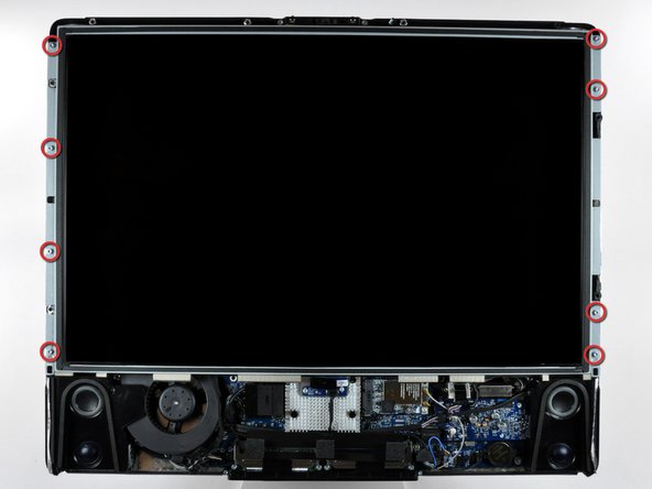
After removing the front bezel, you need to remove the 8ea 12mm T8 screws around the perimeter of the LCD
-
-
Dieser Schritt ist noch nicht übersetzt. Hilf mit, ihn zu übersetzen!
-
Use the chart provided as a reference and test the various voltages with your meter being sure to restrict the probes to the 10 solder joints on the PSU connector shown within the BLUE rectangle. Shorting any part of the PCB will almost certainly cause damage to the imac
-
All voltage measurements are taken with PIN 1 as reference (Marked with the YELLOW square). Pin 1 is marked on the board by a dot and is the right hand pin when viewed as shown in photos
-
Reassemble your iMac in reverse order. When lowering the LCD ensure you don't crimp or crush the LCD back-light cables
-


Rückgängig: Ich habe diese Anleitung nicht absolviert.
20 weitere Nutzer:innen haben diese Anleitung absolviert.

Team

10 Kommentare
Something I don't get…
I'm investigating on my mid2007 iMac power problems and I don't get the same results of voltage as in this article. In my case, number 9 is at around 12V and number 8 is at 0V.
Is my PSU really faulty or there might be some other PSU models?
I've got the same results as you. Wondering if we have the wrong ps model, despite being what iFixit recommends and sells. Very odd.
i have the same issue. Do we have the wrong power supply or the wrong voltage chart?
Have also the same, maybe the table here is wrong. What kind of problems does your mac have?