Einleitung
Dies ist nur eine grundständige Anleitung. Hierbei werden die meisten Stecker getrennt und die meisten Schrauben entfernt, um das Motherboard zu herauszunehmen. Die Bilder sind so aufgenommen, dass nicht ersichtlich ist, ob die Taptic Engine entfernt wurde oder nicht.
Hinweis: Das Logic Board und der Touch ID Fingerabdrucksensor von jedem iPhone sind ab Werk gekoppelt, sodass der Austausch des Logic Boards die Touch ID deaktiviert, es sei denn du baust auch einen Ersatz Home Button ein, der korrekt mit deinem neuen Logic Board gekoppelt wurde.
Das Öffnen des iPhone 8 beschädigt die wasserfesten Dichtungen am Display. Wenn du diese Klebedichtungen nicht ersetzt, wird dein iPhone zwar normal funktionieren, aber nicht mehr wasserfest sein.
Was du brauchst
-
-
Benutze das flache Ende eines Spudgers, um den Stecker des Kamerakabels zu trennen, indem du ihn gerade aus seinem Anschluss nach oben hebelst.
-
-
-
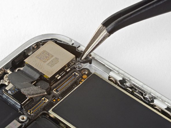
Entferne die beiden Schrauben, mit denen die Halterung der Rückkamera befestigt ist:
-
Eine 3 mm Distanzschraube
-
Eine 3,1 mm Kreuzschlitzschraube
The screw and standoff are the other way round in this step. The photo shows the small screw removed and the standoff securing the logicboard is circled incorrectly. Also you may find that the standoff screw is not magnetic, making it a little tricky to replace!
Hi Michael,
You are correct; thanks for catching that! The original image was correct, and for some reason the image was updated, and no longer correct. I have reverted it back to the original image.
These screws are not magnetized! If you are trying to put them back, use some tweezers to align them, and while still using the tweezers, grab your standoff driver and push down, then you can screw it in with ease.
Thanks for the tip.
Habel -
-
-
-
Benutze die Spitze eines Spudgers, um den Stecker des Blitzes gerade aus seinem Anschluss nach oben zu hebeln und somit zu trennen.
-
-
-
Entferne die beiden Schrauben, mit denen die obere Kabelhalterung befestigt ist:
-
Eine 2,9 mm Kreuzschlitzschraube
-
Eine 1,3 mm Kreuzschlitzschraube
Logically - one wouldn’t need to take out all these things to take out something at the bottom of the phone - but in order to get good access to it, you must remove the logic board - which is long and all the way up at the top connected to the antenna. Follow the steps - it works.
-
-
-
-
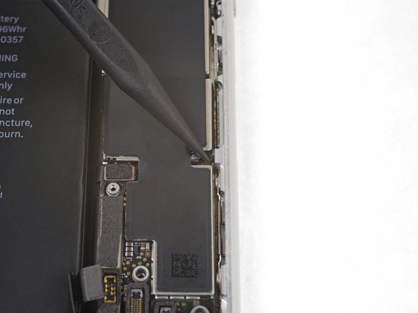
Benutze das flache Ende eines Spudgers, um den oberen Kabelstecker aus seinem Anschluss zu hebeln.
-
-
-
Entferne die drei 1,3 mm Kreuzschlitzschrauben, die die obere linke Antennenkomponente befestigen.
-
-
-
Entferne die 1,4 mm Kreuzschlitzschraube, die die Antennenkomponente an der Oberkante des Gehäuses befestigt.
Be careful not to strip this screw...I did and I'm going to try to proceed without taking off the antenna component.
Update: You can still go on with the replacement if you do not take off the antenna component
I think this screw is stripped on my iPhone , shittt. So I can just skip this part? or what?
If you can avoid putting in battery after this screw, that’ll be easier. I wound up using bit only with my fingers to get an initial thread going.
-
-
-
Entferne die Antennenkomponente.
-
-
-
Entferne die beiden Kreuzschlitzschrauben, mit denen die Erdungsklammer an der oberen linken Kante des Logic Boards befestigt ist:
-
Eine 1,5 mm Kreuzschlitzschraube
-
Eine 2,6 mm Kreuzschlitzschraube
-
-
-
Entferne die Erdungsklammer.
what happen if don't put this part?
Hi Albert,
It’s hard to tell. Most phone functions will probably work, but you may start getting quirky problems.
If it comes out it must go back in *no spare parts *
J'aurais plutôt dit "...le câble de mise à la masse"
Bonjour @roroancet, merci beaucoup de votre remarque ! Cela nous a donné l'occasion de plonger dans l'univers de l'électricité ! Il s'avère ainsi que la mise à la masse est le terme approprié ici. J'ai corrigé notre erreur. La prochaine fois, n'hésitez pas à le faire vous-même. iFixit est un wiki modifiable par tout le monde. Encore merci pour votre attention !
-
-
-
Entferne die drei Schrauben, die das Motherboard befestigen:
-
Eine 1,8 mm Kreuzschlitzschraube
-
Eine 2,5 mm Distanzschraube
-
Eine 2,2 mm Distanzschraube
The One 1.8 mm Phillips screw was buried under some gasket material. It took some twezzer work to get that material off.
this is probably the most difficult part because the ‘top 2.5 mm on my version was under a piece of ribbon cable that had to be pulled back. Also notice - this picture is inverted. So the locations are reversed (obviously for clarity)
Buried 1.8mm Phillips easily located under the gasket material by zooming in on the photo to see position relative to connectors. Material is fibrous, so be patient.
I’ve been searching on internet about the black stickers on those parts in the phone and I found nothing about them, what are they? Electrical Tapes? Does it make any differences if we remove them? If yes is, there anything else we can use to replace them? We’re they are for any specific purposes? Thanks in advance if anyone can help me understand
-
-
-
Biege die Erdungshalterung des Logic Boards vorsichtig mit einer Pinzette weg.
-
-
-
Schiebe den Auswurfkolben der SIM Karte mit der Spudgerspitze aus dem Weg des Logic Boards.
-


Um dein Gerät wieder zusammenzubauen, folge dieser Anleitung in umgekehrter Reihenfolge.
Entsorge deinen Elektromüll fachgerecht.
Lief die Reparatur nicht wie geplant? Bei der iPhone 8 Answers Community kannst du Hilfe finden.
Um dein Gerät wieder zusammenzubauen, folge dieser Anleitung in umgekehrter Reihenfolge.
Entsorge deinen Elektromüll fachgerecht.
Lief die Reparatur nicht wie geplant? Bei der iPhone 8 Answers Community kannst du Hilfe finden.
Besonderer Dank geht an diese Übersetzer:innen:
100%

Diese Übersetzer:innen helfen uns, die Welt zu reparieren! Wie kann ich mithelfen?
Hier starten ›


When replacing, used iFixit tweezers to gently hold/bend the cable, and used my finger to press the connector back in place. This was the best way I could get the connector lined up and seated properly.
Habel - Antwort