Diese Version enthält möglicherweise inkorrekte Änderungen. Wechsle zur letzten geprüften Version.
Was du brauchst
-
Dieser Schritt ist noch nicht übersetzt. Hilf mit, ihn zu übersetzen!
-
Locate the six screws on the outside of the camera (2 3.3 mm on the bottom, 2 5.25 mm on the left, and 2 5.25 mm on the right).
-
Using a Phillips 00 screwdriver, remove all of the six screws.
-
-
Dieser Schritt ist noch nicht übersetzt. Hilf mit, ihn zu übersetzen!
-
Carefully pull the front and back case apart.
-
-
Dieser Schritt ist noch nicht übersetzt. Hilf mit, ihn zu übersetzen!
-
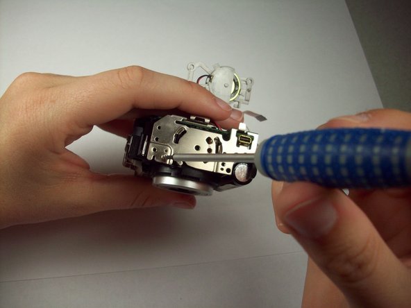
Look closely at the connection between the ribbon cable and the motherboard. Locate the two grey tabs on either side of the connecting bracket.
-
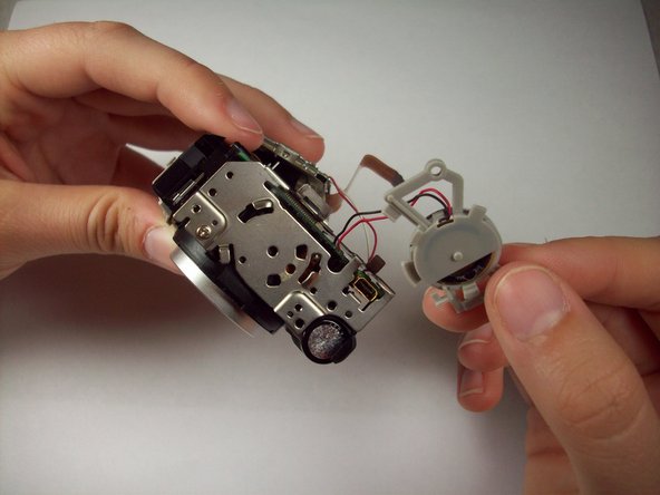
Slide the grey tabs toward the bottom of camera. Gently disconnect the ribbon cable from the motherboard.
-
After disconnecting the data ribbon, you can now separate the back case from the front case.
-
-
Dieser Schritt ist noch nicht übersetzt. Hilf mit, ihn zu übersetzen!
-
With the lens facing down and the bottom of the camera facing away from you, lift up the right edge of the LCD screen (left side of the screen will be glued down).
-
Insert plastic tool under the screen and gently pry up the left side of the screen until the glue seal is broken.
-
-
Dieser Schritt ist noch nicht übersetzt. Hilf mit, ihn zu übersetzen!
-
Locate the orange ribbon cable and two wires (red and white) attached to the motherboard.
-
Lift up on the black clamp and pull out data cable.
-
The screen should now be completely free from the camera.
-
-
-
Dieser Schritt ist noch nicht übersetzt. Hilf mit, ihn zu übersetzen!
-
Locate and remove the four 4.25 mm screws on the motherboard using a Phillips 00 screw driver.
-
-
Dieser Schritt ist noch nicht übersetzt. Hilf mit, ihn zu übersetzen!
-
Remove the ribbon cable on the top right of the motherboard. To remove the cable, slide the two grey tabs, located on both sides, towards the top of the camera and gently pull the cable out.
-
-
Dieser Schritt ist noch nicht übersetzt. Hilf mit, ihn zu übersetzen!
-
Turning the camera to the left and tilting it up, look at the left end of the motherboard to locate the grey bracket.
-
Twist the grey bracket counter clockwise to remove it from the silver LCD bracket.
-
-
Dieser Schritt ist noch nicht übersetzt. Hilf mit, ihn zu übersetzen!
-
Using a Phillips 00 screwdriver, remove the 4.25 mm screw on bottom left edge of the LCD bracket.
-
Lift off the LCD bracket and slip the grey bracket through the LCD bracket. The LCD bracket should now be completely removed.
-
-
Dieser Schritt ist noch nicht übersetzt. Hilf mit, ihn zu übersetzen!
-
Desolder the wire (both black and red) from the motherboard.
-
Remove the orange ribbon cable. This is done by sliding each side of the lock bar toward the center of the camera. Gently pull on the ribbon cable to remove.
-
-
Dieser Schritt ist noch nicht übersetzt. Hilf mit, ihn zu übersetzen!
-
Gently peel back the black tape on the bottom, middle of the motherboard. Underneath you will find a screw.
-
Remove the 4.25 mm screw with a Phillips 00 screwdriver.
-
-
Dieser Schritt ist noch nicht übersetzt. Hilf mit, ihn zu übersetzen!
-
Gently pull the motherboard away from the lens.
-
Flip the camera over.
-
Connecting the motherboard to the front case are seven wires.
-
Desolder the seven wires.
-
-
Dieser Schritt ist noch nicht übersetzt. Hilf mit, ihn zu übersetzen!
-
The AV port is soldered directly onto the back of the motherboard
-


Rückgängig: Ich habe diese Anleitung nicht absolviert.
Ein:e weitere:r Nutzer:in hat diese Anleitung absolviert.
Team

Cal Poly, Team 9-43, Regan Spring 2012 Mitglied von Cal Poly, Team 9-43, Regan Spring 2012
CPSU-REGAN-S12S9G43
5 Mitglieder
12 Anleitungen geschrieben