Ivar O, yes it absolutely is. I do that with old CCFL panels. Those make great reading lights:-) In order to get it accomplished we will need to at least have the number for the panel. I am certain that your will have an LCD backlight, so your power demands will be a lot less than the CCFL monitors. Post a couple images of your panel so we can see the wiring as well.
Okay so your LED driver is a LP8550 with these brief specs:
High-voltage DC/DC boost converter with integrated FET with four switching frequency options: 156/312/625/1250 kHz
2.7V – 22V input voltage range to support 1x…5x cell Li-Ion batteries
Programmable PWM resolution
-8 to 13 true bit (steady state)
-Additional 1 to 3 bits using dithering during brightness changes
I 2C and PWM brightness control
Automatic PWM & current dimming for improved efficiency
PWM output frequency and LED current set through resistors
Optional synchronization to display VSYNC signal
6 LED outputs with LED fault (short/open) detection
Low input voltage, over-temperature, over-current detection and shutdown
Minimum number of external components
Micro SMD-25 package, 2.466 x 2.466 x 0.6 mm
This will help us to determine what voltage you need for the input.
Further parameters of this IC are :
Vin (Min) (V) 5.5V
Vin (Max) (V) 22
Vout (Max) (V) 40
Iout (Max) (A) 400
Shutdown Current (Typ) (uA) 1
Iq (Typ) (mA) 4
LED (#) 60
LED Configuration series
LED Current Per Channel (mA) 30
Here is one way to build a driver circuit for your LED backlight
Next is an image of your LCD connector. Pin 6-11 are the backlight connections
This is where the importance of your LVDS cable comes in handy. You can now either traces the wires from your connector to the panel, or use the connector and purchase the female part that is usually on the logicboard, to build your driver. the connectors are available at places like this as well as many others
So, again, you could use the IC typical application, or you could emulate the backlight driver circuit that your computer uses. Here is the schematic for that.
There is another thing you could do. That is to get a commercially available DC-DC converter that is capable of producing the proper voltages. Those are pretty much available at ebay.com as well as many other places. Then connect that to your panel using the pins as specified.
This is definitely a great project to continue to use old LCD panels.
Hope this helps, good luck.
War diese Antwort hilfreich?
Bewertet
Rückgängig machen
Bewertung
2
Abbrechen
Schau durch den Thread, bis du den richtigen Platz für diesen Kommentar gefunden hast. Klicke dann auf "Den Kommentar diesem Post zuordnen", um ihn zu verschieben.


3 Kommentare
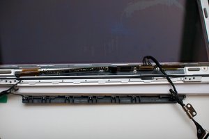
Hi again, I have found the part number for the LED strip in my screen. It is QT001A-S265-0G. I can't find a pinout. On the back of the inverter board (or the screen controller or whatever, I guess it's not an inverter board really) it says DCN202602L3DN57A5 LGD LP116WH4 TJA3 116B151401TAW 411A. Googling for LP116WH4 TJA3 tells me that I have an LG panel with this name, without backlight, meaning that the LED backlight is a separate part from the LCD. This link: http://www.panelook.com/LP116WH4-TJA3_LG... tells me that the signal interface to this LCD is eDP (1 lane), this is short for embedded display port, so it should be following a standard. I'm still hoping someone can help me sort this out, so I can power the LED backlight either through the LVDS cable, or directly to the flat connector on the LED strip.
All the best, Ivar
von Ivar O
Ivar O, any chance for some Hires images of the board that is connected to your Display? Specially around the connector area.....
von oldturkey03
just an FYI:" the lack of standardization in the industry of LED backlight configuration and LED connectivity. Inside the backlight, there are some similarities in the way panel manufacturers configure the LEDs. This configuration tends to be in multiple banks of series-connected LEDs, but that is where the similarities end. Some manufacturers choose a common anode connection, some choose a common cathode configuration, and others choose a separate cathode and anode connection for each bank. This lack of standardization makes it difficult for designers to address the connectivity of LED drivers. The solution provided by some manufacturers is to add flexibility to support any and all of these configurations. from here
von oldturkey03