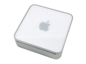
Broken motherboard power plug
Plan to remove the motherboard after removing the internal frame in my MacMin 3,1 (late 2009) to clean out the filthy box,
Apple says to pull the very thin power cable straight up from the motherboard that connects it to the rear shelf button. What happened to me was the motherboard flat plug BROKE at both pins flush with the logic board. The is nothing to solder to.
Is there a workaround to reconnect the two line cable from the rear power button to the motherboard? I see nothing to solder to on the motherboard with no protruding pin parts as I had hoped to see.
Thanks! W. Li
Update (03/18/2017)
Dan
Here it is.....

Ist dies eine gute Frage?

 8
8  3
3  2
2 


4 Kommentare
Can you take a picture of the connector and the location on the logic board so we know which connection you damaged.
Here's the IFIXIT guide to remove the logic board if might help you in locating the connection: Mac mini Model A1283 Logic Board Replacement
von Dan
Its best to just post the images here within a answer. In the menu to the far right is the media eager just click it to add your stuff.
von Dan
SUCESS! Thanks to both Dan and Minho. I am ashamed to admit that I was way too rough fooling around with the MB. So calmed down and with my 4x loupes re-examined the MB and probed around using a ohmmeter (using the rx1 range using only 1.5v). Here is what I found (see attached picture). The upper trace went to one end of coil L4800. The lower trace went to the large semicircular grounding pad. By soldering 30G wires to these points and connecting them up the OEM power button... the unit powered up just fine.
Thanks again all!
von wli98122
Nice attached picture
von davidking0001