Zum Hauptinhalt wechseln

{A1706 / EMC 3071}—Veröffentlicht im Juni 2017. Dieses 13" Macbook Pro ist mit Kaby Lake Prozessoren bis zu 3,5 GHz Core i7 mit Turbo Boot bis zu 4,0 GHz ausgestattet.

276 Fragen Alle anzeigen

Fan stuck on max immediately after boot. (Thermal Paste Replaced)

Macs Fan Control temps are all normal ( 35-40˚C) but the right fan is stuck at 8800~ rpm when it should have been 6864 rpm at max. I did try reinserting and cleaning all the cables connected to the logic board as well as resetting the SMC but the problem persists.

Apple diagnostics show an error of PPF03, meaning a fan data control line might be the cause. Does anyone know where that data line is? Or if so, which of the cables connected to the logic board is responsible for the fans?

UPDATE: Searching the internet, it may be a sensor issue, but all sensors seem to be normal. (Here is a screenshot; In case something is missing)

Block Image

Update (10/25/2019)

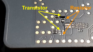
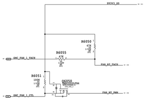
Update: Soo I have obtained the schematics and the circuit which controls the fan speed has transistors Q6000 and Q6050. Upon rechecking my board, get this.

Block Image

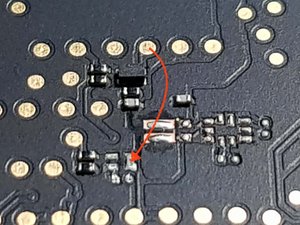
Looking a bit closer, there should be two small black boxes, one on top and the other on the bottom.

Block Image

It seems that upon reassembly, these components were scraped from their pads. Problem is, I can't find them. Pretty hard to buy one either.

Beantwortet! Antwort anzeigen Ich habe das gleiche Problem

Ist dies eine gute Frage?

Bewertung 2
1 Kommentar

Looks like you are missing:

- Q6050, Diodes Inc. DMN32D2LFB4R6051

https://octopart.com/search?q=DMN32D2LFB...

- R6051, 100k 5% 1/20W 0201 resistor

https://octopart.com/search?q=100k+1%2F2...

Not sure about the components to the right of this, which are related to backlight current sensing.

- R5730, 1% 1/3W

https://octopart.com/erj-3lwfr005v-panas...

-U5730, Opamp INA210, UQFN

https://octopart.com/search?q=INA210+UQF...

von

Einen Kommentar hinzufügen

2 Antworten

Gewählte Lösung

The error is a logic board error. You’ll need to trace out the logic to find the defect.

Sadly, Apple has done a good job controlling their schematics and board view drawings. The only thing out their is an incomplete schematic & drawing which is missing the fan control logic.

You’ll need to bring in or ship your system to Apple for repair. Do you have AppleCare+ that will soften the bite otherwise its quite expensive.

Your other option is just replace the logic board your self Mid 2017 13” MacBook Pro retina Touch Bar Logic Boards

We don’t have a proper guide but the MacBook Pro mit Touch Bar (13 Zoll, 2017) Teardown should give you enough information on how its mounted and follow this guide first steps to make sure your system is fully off before starting MacBook Pro (15 Zoll, Ende 2016, Touch Bar) Akku tauschen

Update (10/26/2019)

@mrman - Yes, your logic board is missing some components! Looks like they got snagged.

Block Image

These are the fans tach control logic.

If you can’t find them at one of the part houses or a junker board to steal them then you’ll need to replace the logic board.

MacBook Pro 13" Touch Bar 2017 Bild

Anleitung

MacBook Pro mit Touch Bar (13 Zoll, 2017) Teardown

Schwierigkeitsgrad:

Mittel

MacBook Pro 15" Touch Bar Late 2016 Akku Bild

Anleitung

MacBook Pro (15 Zoll, Ende 2016, Touch Bar) Akku tauschen

Schwierigkeitsgrad:

Schwierig

1 - 3 hours

War diese Antwort hilfreich?

Bewertung 2

4 Kommentare:

Thanks, Dan, for the answer. Sadly, there are no official Apple repair centers in my country, just authorized ones. And they even charge ~45$ just to get it diagnosed and charge me a kidney for a simple fix. I'd rather repair it myself.

In the meantime, I disconnected the said fan for the time being. Temps are still okay thankfully because of the other fan still working.

von

I was able to buy the missing parts but it is extremely tricky to solder them. So, as a last resort attempt, I decided to short the fan PWM pads instead and now the fans are now in sync! Thank you, Dan!

von

@mrman - Don't forget to score the answer and accept it - Thanks!

von

@mrman That last resort attempt sounds like an option that might help me with the same issue as well, would you care to explain in a little more detail what you did?

von

Einen Kommentar hinzufügen

I basically soldered these two pads using magnet wire so that the other fan would spin. It's important to use magnet wire (enamel wire is the same thing) as the wires I use for breadboards never solder properly on the tiny pads.

Block Image


Just don't heat the pad too much because I did and the gold circle pad came off. Luckily I was able to scratch the trace so it had something to stick to.

Below is the schematic of the fan circuit and the FAN_RT_PWM would just connect to the FAN_LT_PWM from the other side.

Block Image

War diese Antwort hilfreich?

Bewertung 1

1 Kommentar:

I'd love to see a picture or video.better demonstrating what you did!

von

Einen Kommentar hinzufügen

Antwort hinzufügen

Victor Emmanuel Baylosis wird auf ewig dankbar sein.
Seitenaufrufe:

Letzte 24 Stunden: 3

Letzte 7 Tage: 6

Letzte 30 Tage: 22

Insgesamt: 1,039