Zum Hauptinhalt wechseln

Dieser Teardown ist in Bearbeitung – Lade die Seite regelmäßig neu, um die neuesten Änderungen zu sehen!

Was du brauchst

  1. Cuisinart 4-Slice Tandem Toaster Teardown, Cuisinart 4-Slice Tandem Toaster Teardown: Schritt 1, Bild 1 von 1
    • This Cuisinart Toaster's technical highlights include:

    • Tandem, 2-slot toaster

    • 1½" wide toasting slots

    • Function control dial

    • Bagel, Defrost and Reheat selections

    • Blue LED shade control with large, easy-to-read numbers

    • 2 or 4 slice button; cancel button

  2. Cuisinart 4-Slice Tandem Toaster Teardown: Schritt 2, Bild 1 von 2 Cuisinart 4-Slice Tandem Toaster Teardown: Schritt 2, Bild 2 von 2
    • Unplug the toaster prior to teardown.

    • On the bottom of the toaster, unscrew the 4 Torx screws (using a screw driver)

  3. Cuisinart 4-Slice Tandem Toaster Teardown: Schritt 3, Bild 1 von 3 Cuisinart 4-Slice Tandem Toaster Teardown: Schritt 3, Bild 2 von 3 Cuisinart 4-Slice Tandem Toaster Teardown: Schritt 3, Bild 3 von 3
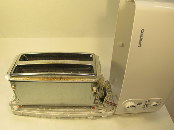
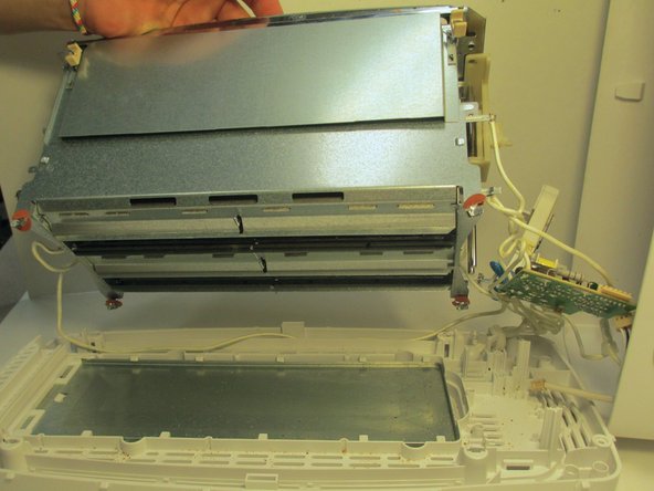
    • Pull the press handle down and away from the toaster to disconnect the body.

    • Lift up the body of the toaster.

  4. Cuisinart 4-Slice Tandem Toaster Teardown: Schritt 4, Bild 1 von 1
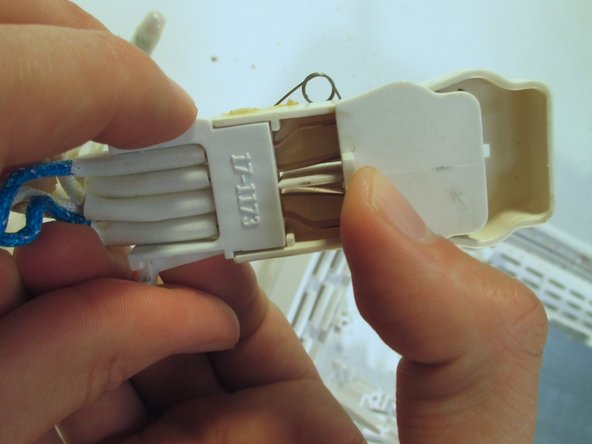
    • Pull the pin header cable to disconnect the body of the toaster from the main assembly unit.

  5. Cuisinart 4-Slice Tandem Toaster Teardown: Schritt 5, Bild 1 von 3 Cuisinart 4-Slice Tandem Toaster Teardown: Schritt 5, Bild 2 von 3 Cuisinart 4-Slice Tandem Toaster Teardown: Schritt 5, Bild 3 von 3
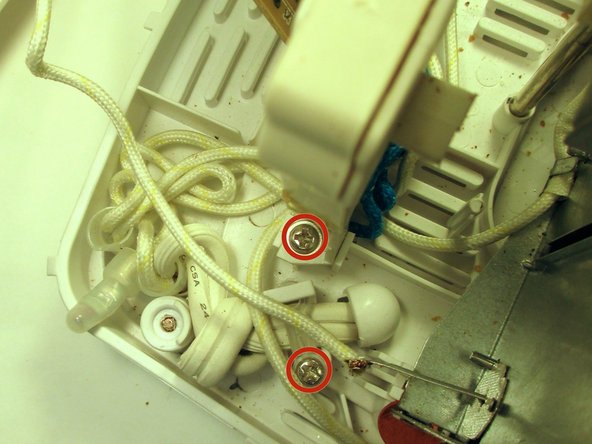
    • Remove the 5 Torx screws to detach the heating unit from the bottom of the toaster unit.

  6. Cuisinart 4-Slice Tandem Toaster Teardown: Schritt 6, Bild 1 von 3 Cuisinart 4-Slice Tandem Toaster Teardown: Schritt 6, Bild 2 von 3 Cuisinart 4-Slice Tandem Toaster Teardown: Schritt 6, Bild 3 von 3
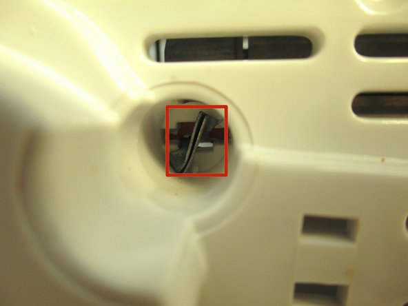
    • Using a plastic opening tool, carefully pry open the metal casing underneath the toaster.

  7. Cuisinart 4-Slice Tandem Toaster Teardown: Schritt 7, Bild 1 von 3 Cuisinart 4-Slice Tandem Toaster Teardown: Schritt 7, Bild 2 von 3 Cuisinart 4-Slice Tandem Toaster Teardown: Schritt 7, Bild 3 von 3
    • Remove the screws to detach controls from the plastic shell of the toaster.

  8. Cuisinart 4-Slice Tandem Toaster Teardown: Schritt 8, Bild 1 von 1
    • Interior of the user control interface

  9. Cuisinart 4-Slice Tandem Toaster Teardown: Schritt 9, Bild 1 von 1
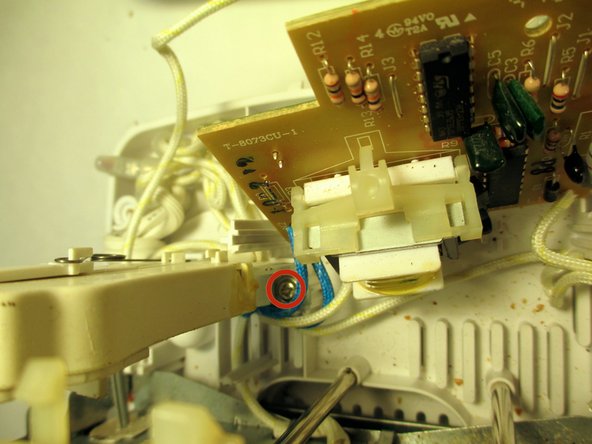
    • Remove the soldered wire that is hooked to each part of the end plate assembly.

  10. Cuisinart 4-Slice Tandem Toaster Teardown: Schritt 10, Bild 1 von 2 Cuisinart 4-Slice Tandem Toaster Teardown: Schritt 10, Bild 2 von 2
    • Heating Unit

  11. Cuisinart 4-Slice Tandem Toaster Teardown: Schritt 11, Bild 1 von 1
    • This is the Circuit Board used for controlling each subsystem of the toaster.

    • The integrated circuit marked 4541 contains an oscillator which oscillates at some hundreds or thousands of oscillations per second, the speed being determined by the browning setting. It also contains a binary counter which can count up to 65,536.

    • The integrated circuit marked 4066 contains several logic gates which select the count value required for normal, defrost or reheat.

    • During the count, the logic gates supply a small current to the transistor, causing it to energise the electromagnet. At the end of the selected count, the logic gates switch this current off and the transistor de-energises the electromagnet.

    • While energised, the electromagnet holds the lever down. When the current is switched off the lever is released and the spring pops the toast up.

    • Toasters of this age frequently use these "4000-series" integrated circuits as they can run off a wide range of supply voltages. Newer toasters use a microcontroller (essentially a simple micro computer) as this is more flexible in its functions and can also easily drive LEDs to show you what the toaster is doing.

  12. Cuisinart 4-Slice Tandem Toaster Teardown: Schritt 12, Bild 1 von 1
    • Main Assembly Unit

  13. Cuisinart 4-Slice Tandem Toaster Teardown: Schritt 13, Bild 1 von 1
    • Main Element Assembly

    • Crumb Tray with Power Cord

    • Circuitry with Heating Component

    • User Control Interface with Buttons

    • Press Handle Spring

Lucas Tintikakis

Mitglied seit: 03/02/14

133 Reputation

1 Anleitung geschrieben

Team

EE460 UNO Mitglied von EE460 UNO

Community

2 Mitglieder

8 Anleitungen geschrieben

3 Kommentare

Have this broken device and would be glad to us this demonstration to fix it!

Robert Scherer - Antwort

Thanks for this great post-up. Saved me a lot of time not having to figure out the disassembly. Hope my comments will further help others trying to do the same.

Cheers!

Keith

K Lynch - Antwort

Muy detallado desmontaje felicitaciones

Carlos López (España - Spain) - Antwort

Kommentar hinzufügen

Seitenaufrufe:

Letzte 24 Stunden: 2

Letzte 7 Tage: 10

Letzte 30 Tage: 45

Insgesamt: 6,106