Was du brauchst
-
Dieser Schritt ist noch nicht übersetzt. Hilf mit, ihn zu übersetzen!
-
The Emerson Research SmartSet alarm clock automatically sets the time through the power of black magic and voodoo when plugged in.
-
That pale blue display, while calming during the day, while be so bright as to make it nearly impossible to sleep at night.
-
That said, let’s tear it apart.
-
-
Dieser Schritt ist noch nicht übersetzt. Hilf mit, ihn zu übersetzen!
-
Remove 5/16” screw and slide out battery tray.
-
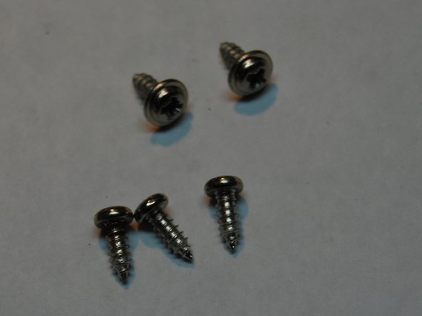
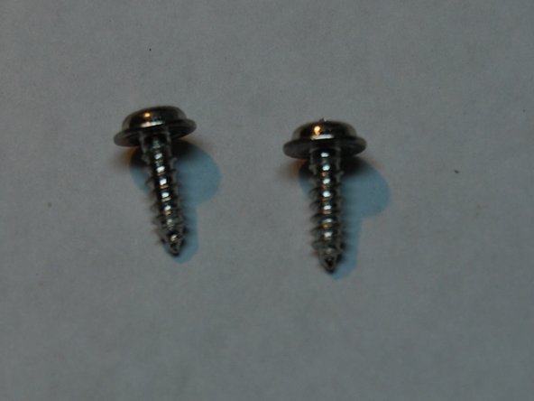
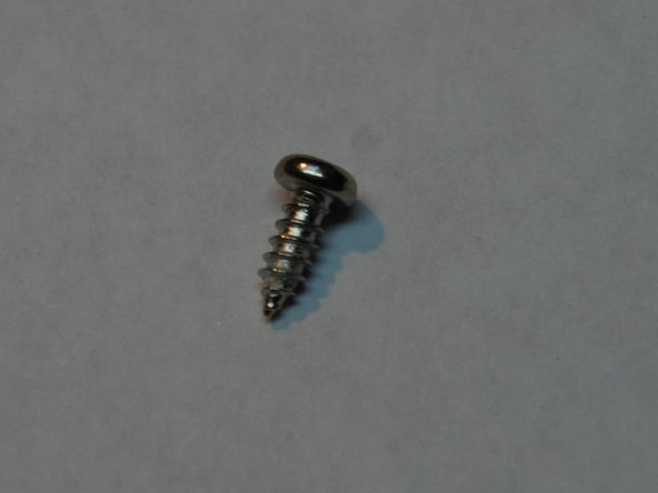
Remove four 1” screws.
-
Note the address on the ID sticker. Maybe send them a Christmas card and see if they send one back.
-
-
Dieser Schritt ist noch nicht übersetzt. Hilf mit, ihn zu übersetzen!
-
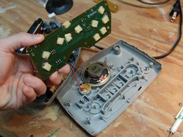
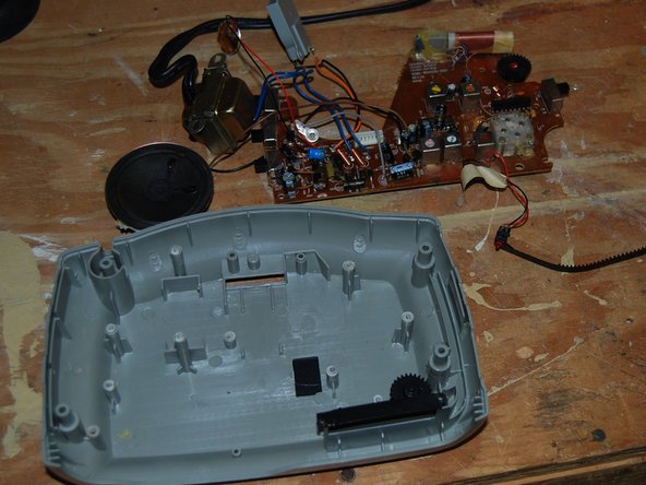
Carefully, pulling from front to rear, pull away lid from bottom shell and display cover.
-
Grip ribbon connector by corners (not wires) and pull straight back away from board connector.
-
-
Dieser Schritt ist noch nicht übersetzt. Hilf mit, ihn zu übersetzen!
-
Gently lay lid flat. Imagine it’s a sandwich you don’t want to upset
-
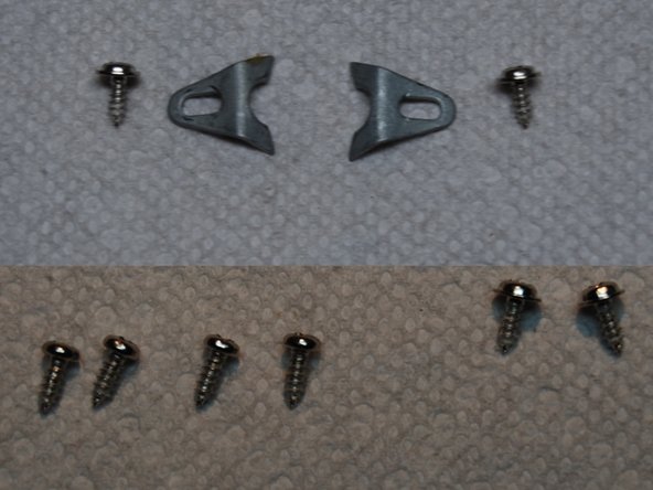
Remove two 5/16” screws and two speaker brackets.
-
Remove four 5/16” screws from board.
-
Remove two more 5/16” screws from board.
-
Remove the board. Appreciate how easy everything’s been so far.
-
-
Dieser Schritt ist noch nicht übersetzt. Hilf mit, ihn zu übersetzen!
-
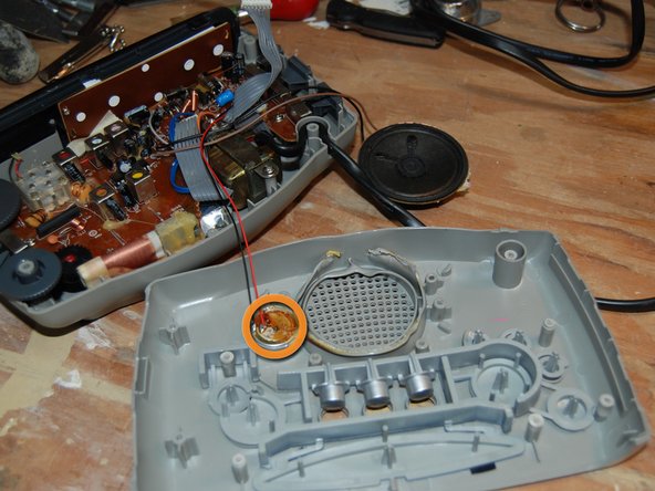
Carefully heat the glue along the plastic frame of the speaker. It will be difficult to heat the glue without deforming the plastic frame, as gratuitous amounts of glue were used and the frame wilts at the mere suggestion of heat. For those of you who can shoot fine lasers from your eyes, this would be a fine time to utilize that skill.
-
Pull the speaker away. If you’re patient, you might be able to pull out the speaker without damaging the frame too badly. If patience eludes you, as soon as you apply heat, get something to use as a wedge, start prying, and pray for the best.
-
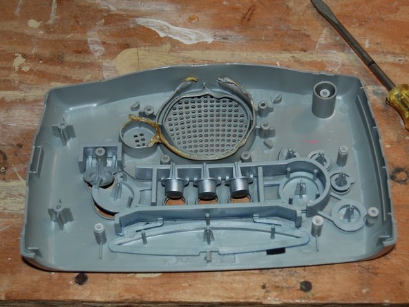
Carefully heat and remove chime. This is much easier to remove than the speaker.
-
-
Dieser Schritt ist noch nicht übersetzt. Hilf mit, ihn zu übersetzen!
-
Once you pull away the Sleep/Snooze buttons away from lid, the lid is disassembled.
-
Congratulations. Hard part over.
-
-
Dieser Schritt ist noch nicht übersetzt. Hilf mit, ihn zu übersetzen!
-
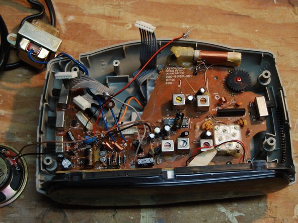
Moving on to the bottom shell....
-
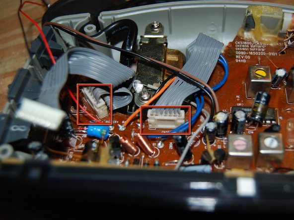
Remove two ribbon connectors from board. Grip each ribbon connector by corners (not wires) and pull straight up and away from board connector.
-
-
-
Dieser Schritt ist noch nicht übersetzt. Hilf mit, ihn zu übersetzen!
-
Remove two 9/16” screws from power source.
-
Remove power source from bottom shell.
-
-
Dieser Schritt ist noch nicht übersetzt. Hilf mit, ihn zu übersetzen!
-
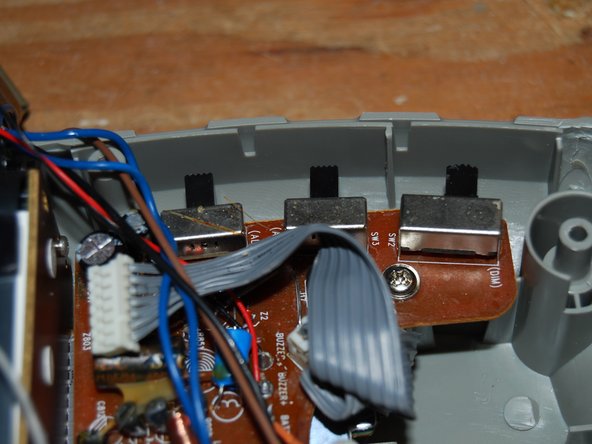
Remove three selector switches. They pull off easily. Note their locations. Or play Tetris later figuring out where they go.
-
-
Dieser Schritt ist noch nicht übersetzt. Hilf mit, ihn zu übersetzen!
-
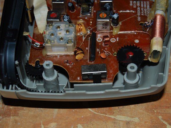
Remove one selector switch...
-
...and two thumb knobs.
-
-
Dieser Schritt ist noch nicht übersetzt. Hilf mit, ihn zu übersetzen!
-
Remove three 5/16” screws...
-
...and two more 5/16” screws.
-
-
Dieser Schritt ist noch nicht übersetzt. Hilf mit, ihn zu übersetzen!
-
Rotate board so that two screws securing the display board are accessible.
-
Remove two 3/8” screws.
-
-
Dieser Schritt ist noch nicht übersetzt. Hilf mit, ihn zu übersetzen!
-
Slide main board and display board forward to access battery tray connector.
-
Remove 5/16” screw.
-
Remove battery tray connector by pulling the connector away from the bottom shell.
-
-
Dieser Schritt ist noch nicht übersetzt. Hilf mit, ihn zu übersetzen!
-
Pull display cover and display board away from bottom shell and set aside.
-
-
Dieser Schritt ist noch nicht übersetzt. Hilf mit, ihn zu übersetzen!
-
Very carefully heat the bracket securing the radio frequency indicator LED assembly. You will likely not be able to do this without breaking it.
-
Pull out radio frequency indicator LED assembly.
-
Separate main board from the bottom shell.
-
-
Dieser Schritt ist noch nicht übersetzt. Hilf mit, ihn zu übersetzen!
-
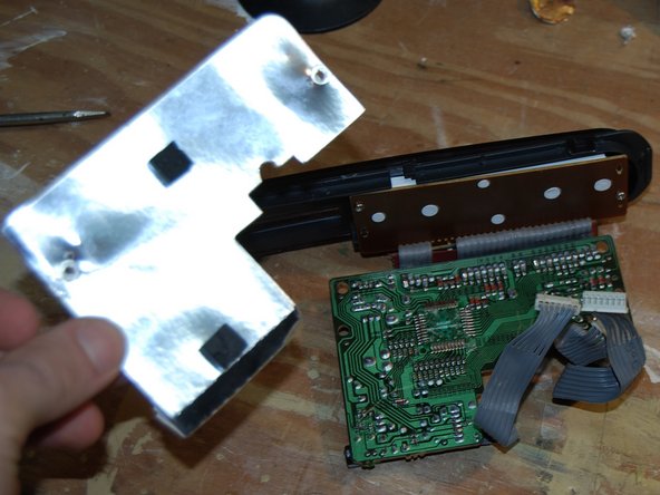
Back to the display....
-
Pull away the reflective shield.
-
-
Dieser Schritt ist noch nicht übersetzt. Hilf mit, ihn zu übersetzen!
-
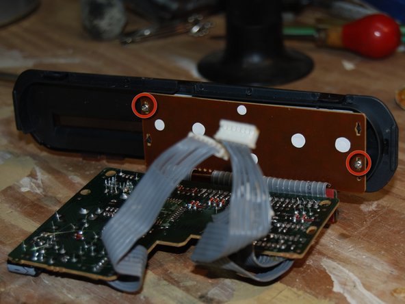
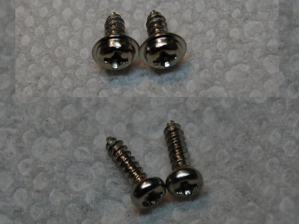
Remove two 5/16” screws.
-
and two more 5/16” screws.
-
Separate the display cover from the display board.
-
-
Dieser Schritt ist noch nicht übersetzt. Hilf mit, ihn zu übersetzen!
-
Separate the display cover from the display board.
-
-
Dieser Schritt ist noch nicht übersetzt. Hilf mit, ihn zu übersetzen!
-
You’re done. Drink a beer. (Or, if you have access to it, a tall glass of horchata.)
-


4 Kommentare
I have a cks3516 can’t set time. Is the power coming out of transformer d.c.? Want to test it! Thinking might be capacitor or cold solder joint! Any help or schematic would be lots of help! This is the projection clock radio! Thank you!
What does suffix D mean on the label. I seen some of the same model without it on the label. Is there a hidden function for home security? Like a microphone or small camera hidden to watch the room its in?
My old clock still works, but not bright enough anymore. Can I alter the circuitry a bit?