Was du brauchst
-
Dieser Schritt ist noch nicht übersetzt. Hilf mit, ihn zu übersetzen!
-
Frontal/Back View- Dimensions: (LxWxD) 107mm x 50mm x 14mm (4.02" x 1.97" x .55") <- For those in America :) Weight: 96g or 3.10oz
-
Speaker
-
Status LED
-
High-res 240x260 Color LCD display
-
Red Trackball
-
1.3MP Camera
-
Flash
-
Back Cover Latch
-
-
Dieser Schritt ist noch nicht übersetzt. Hilf mit, ihn zu übersetzen!
-
Side View!
-
3.5mm Stereo Headset Jack
-
USB 2.0 Data/Charging Port
-
Micro SD Card Slot
-
Camera/Quick Access Button
-
Volume Up/Down Button
-
Quick Access Button
-
Lanyard/Accessory Attachment
-
-
Dieser Schritt ist noch nicht übersetzt. Hilf mit, ihn zu übersetzen!
-
Top/Bottom!
-
This phone his seen it's share of scratches!
-
Mute/Ringer Off Button
-
Microphone
-
-
Dieser Schritt ist noch nicht übersetzt. Hilf mit, ihn zu übersetzen!
-
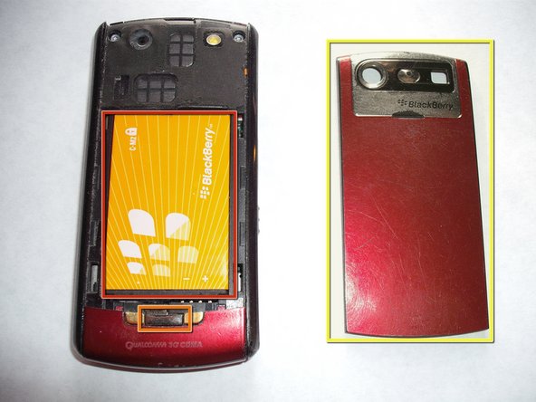
Press down on clip and remove back cover.
-
Push Battery from top to bottom and pull up to remove.
-
Battery: Standby time- 216 hours/Call time- 4 hours
-
Clip
-
Back cover
-
-
-
Dieser Schritt ist noch nicht übersetzt. Hilf mit, ihn zu übersetzen!
-
1.3MP Camera
-
Flash
-
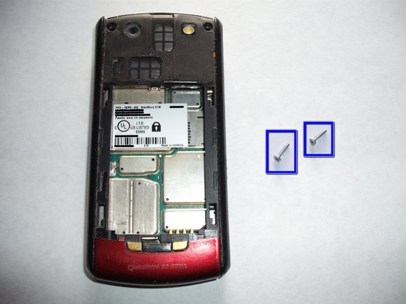
QuALCOMM 3G CDMA
-
Phone information sticker
-
Torx T5 screws
-
-
Dieser Schritt ist noch nicht übersetzt. Hilf mit, ihn zu übersetzen!
-
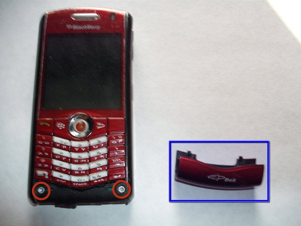
Insert curved point metal spudger into gap between keyboard and bottom bezel cap.
-
Bottom Bezel Cap
-
Pull up and push away to lift bezel.
-
Hold this cap with your thumb and flip the phone around.
-
Insert spudger under bezel and lift on both sides.
-
Pry Here
-
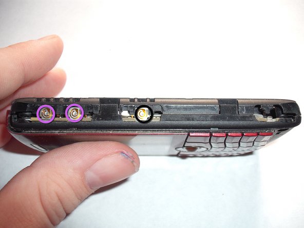
The Bezel Cap should pop off at this point revealing two more T5 screws!
-
Two T5 Screws
-
-
Dieser Schritt ist noch nicht übersetzt. Hilf mit, ihn zu übersetzen!
-
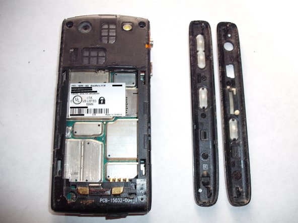
Remove the two T5 Screws and set them aside.
-
The two T5 screws and their respective holes
-
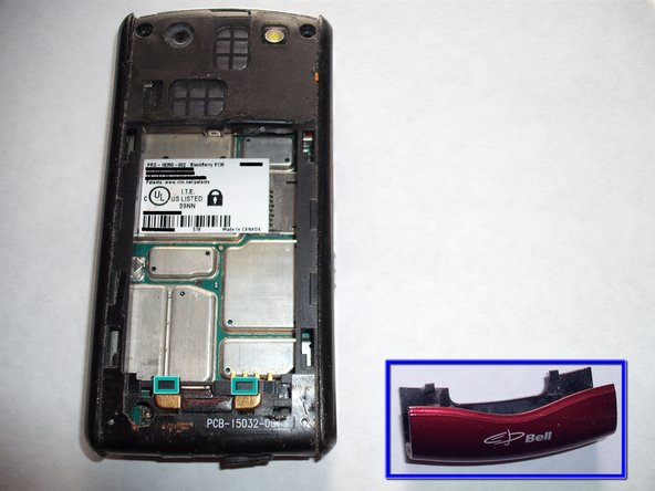
Start at the top of one of the sides of the phone and pry off the silver sides with a spudger or your fingers.
-
Once you have removed both sides set them aside
-
The silver sides
-
Various holes, buttons and slots
-
-
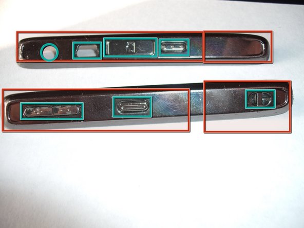
Dieser Schritt ist noch nicht übersetzt. Hilf mit, ihn zu übersetzen!
-
Headphone Jack
-
USB 2.0 Port
-
Micro SD Card Slot
-
Camera Button
-
Up and Down Buttons
-
Quick Access Button
-
-
Dieser Schritt ist noch nicht übersetzt. Hilf mit, ihn zu übersetzen!
-
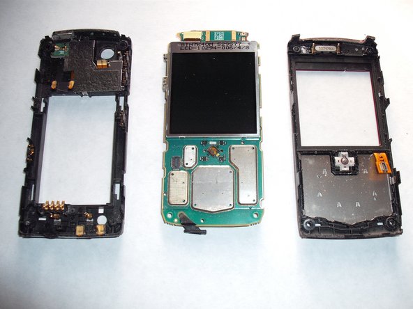
Pry front cover and back cover off of LCD and circuit board.
-
Separate the three parts and set them down.
-
Back plastic assembly
-
LCD and Logic Board
-
Front plastic assembly and keypad+trackball
-
-
Dieser Schritt ist noch nicht übersetzt. Hilf mit, ihn zu übersetzen!
-
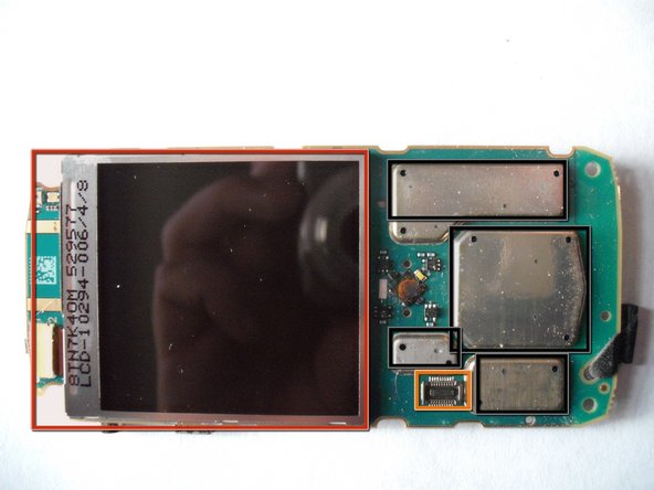
Trackball (Removable). Pop it out from the back.
-
Display Glass (Removable). Pry from the top to break glue seal, pry the rest of with your fingers.
-
Keypad
-
LCD and connector above it to the left (Removable). Remove connector with spudger and free LCD from clips.
-
Keypad connector (Keypad was removed). To remove pry connector up off of logic board.
-
Battery Connector
-
Various chips under metal heat sinks. Sorry I won't remove them the phone is still good and I don't want to risk damaging it :(
-
-
Dieser Schritt ist noch nicht übersetzt. Hilf mit, ihn zu übersetzen!
-
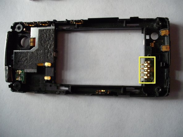
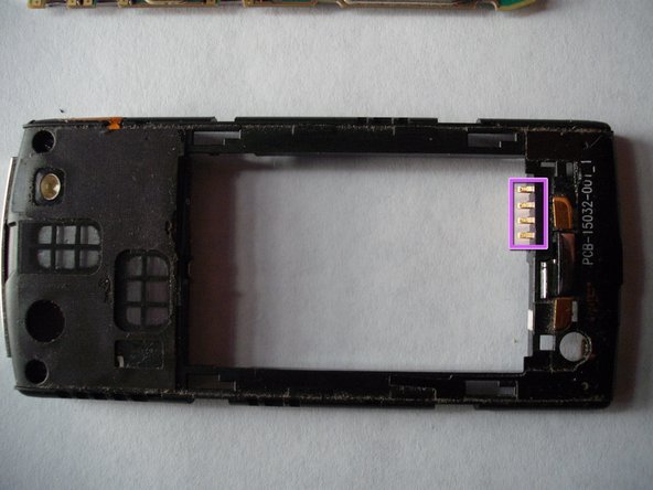
Speaker (Removable by Soldering)
-
Keyboard Connector
-
Trackball (Remove by poking out)
-
1.3MP Camera (Removable by Soldering)
-
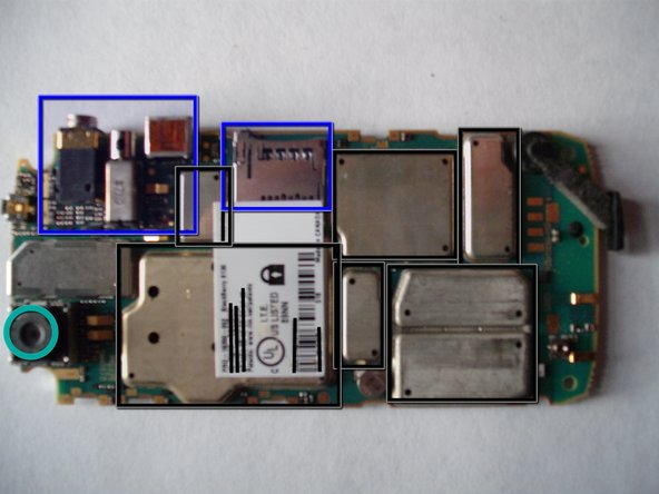
From left to right: Headphone jack, Antenna?, USB Port, Micro SD Card Slot. All of the above are removable by soldering.
-
Battery Connector (Removable by pulling it straight out of it's slot)
-
Various chips covered by heatsinks
-
-
Dieser Schritt ist noch nicht übersetzt. Hilf mit, ihn zu übersetzen!
-
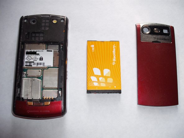
Here it is, everything all laid out.
-
Back Cover and Battery
-
T5 Screws
-
Bezel cap
-
Shiny Side pieces
-
Front Plastic Assembly
-
Back Plastic Assembly
-
LCD and Logic Board
-