Was du brauchst
-
Dieser Schritt ist noch nicht übersetzt. Hilf mit, ihn zu übersetzen!
-
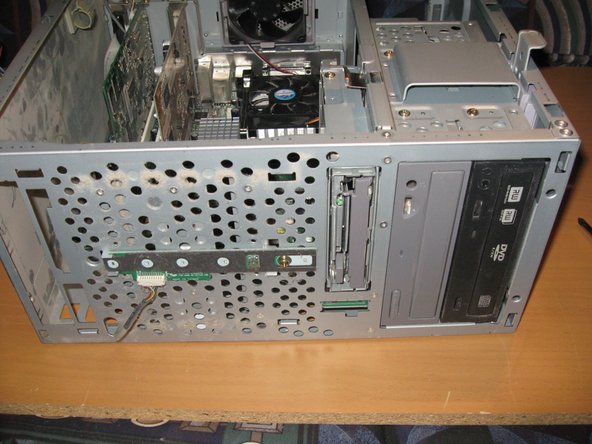
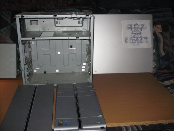
A few pictures of the front and side panels.
-
-
Dieser Schritt ist noch nicht übersetzt. Hilf mit, ihn zu übersetzen!
-
Remove the side panel by unlocking the retaining clips on the rear of the PC and sliding the panel off.
-
You may want to put the PC on its side at this time.
-
-
Dieser Schritt ist noch nicht übersetzt. Hilf mit, ihn zu übersetzen!
-
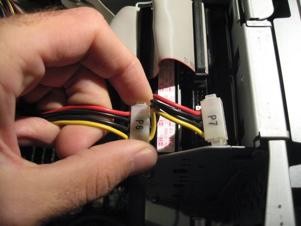
Remove the Power Cables from the Hard Drive(s). These are Molex Connectors
-
Do this by pulling the clip on either side - May require a little force
-
-
Dieser Schritt ist noch nicht übersetzt. Hilf mit, ihn zu übersetzen!
-
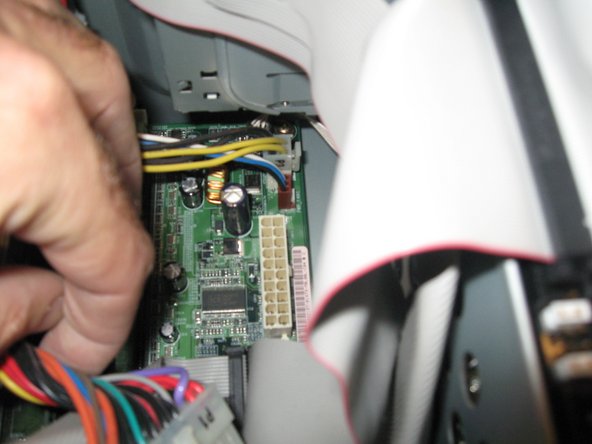
Remove power to the motherboard by finding the 20 pin Connector and disconnecting it.
-
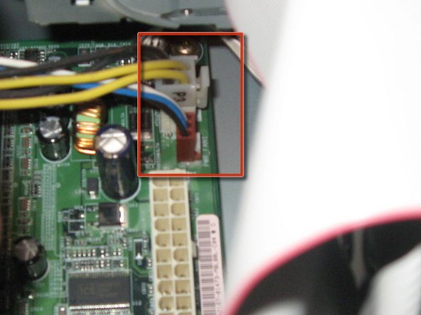
Also remove the 4 pin P3 Connector and the brown mini connection next to it.
-
-
Dieser Schritt ist noch nicht übersetzt. Hilf mit, ihn zu übersetzen!
-
Now remove power from the two Cd/DVD Drives- these are the same Molex connectors as the Hard Drives.
-
Remove Power Cable from the Floppy Drive. - this is known as a mini connector. As shown boxed in Red
-
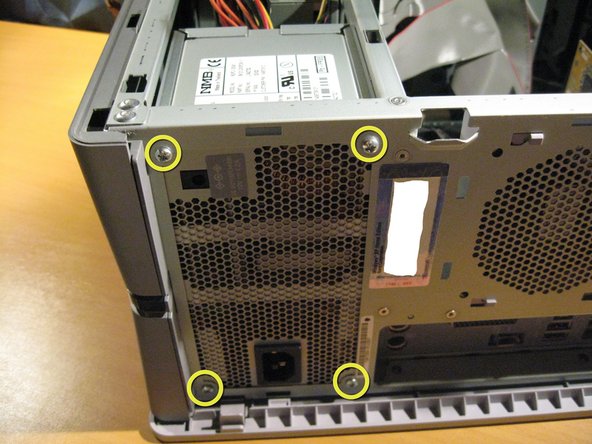
Now That all Power connectors are un-attached, we will remove the power supply.
-
Unscrew four screws (labeled in yellow Circles) Then lift power supply out of Case.
-
-
Dieser Schritt ist noch nicht übersetzt. Hilf mit, ihn zu übersetzen!
-
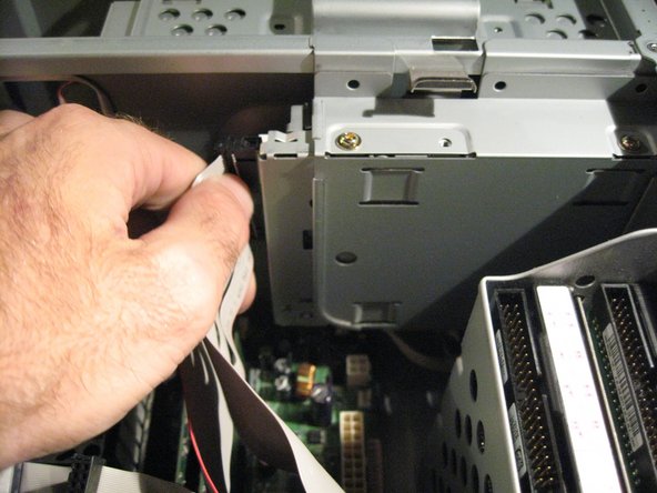
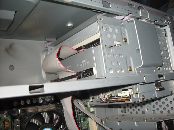
We can now remove the Data Cables- These are called IDE Cables
-
They are removed by simply pulling them out.
-
First from the the Hard Drives then from the Floppy and Disk Drives
-
-
Dieser Schritt ist noch nicht übersetzt. Hilf mit, ihn zu übersetzen!
-
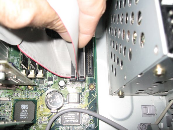
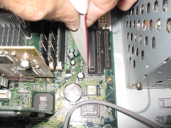
Then Remove the other end of the IDE cables from the Motherboard
-
-
Dieser Schritt ist noch nicht übersetzt. Hilf mit, ihn zu übersetzen!
-
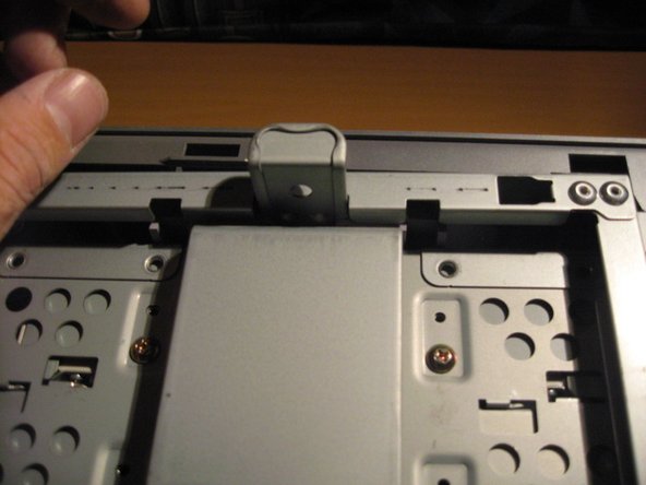
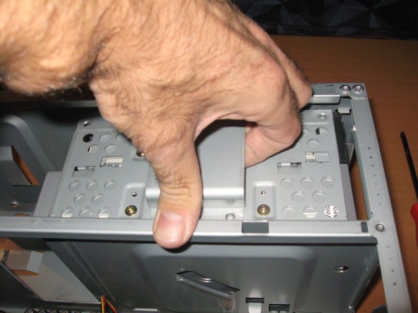
The two Hard Drives have their own seperate encasement
-
Lift up on the Latch as shown
-
Remove the Hard Drive assembly
-
-
Dieser Schritt ist noch nicht übersetzt. Hilf mit, ihn zu übersetzen!
-
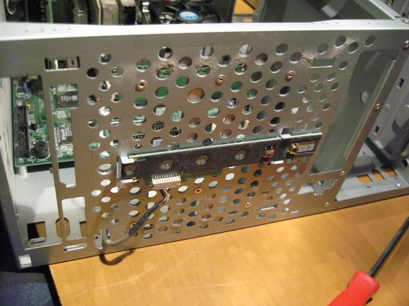
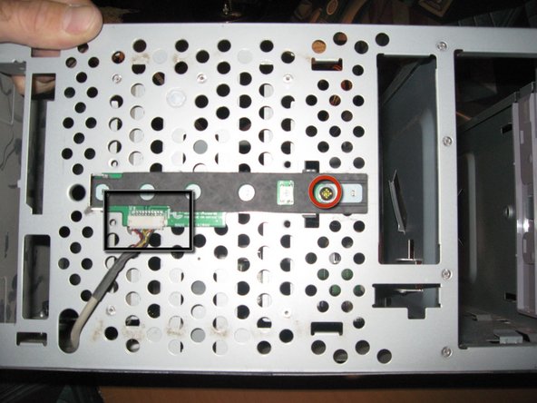
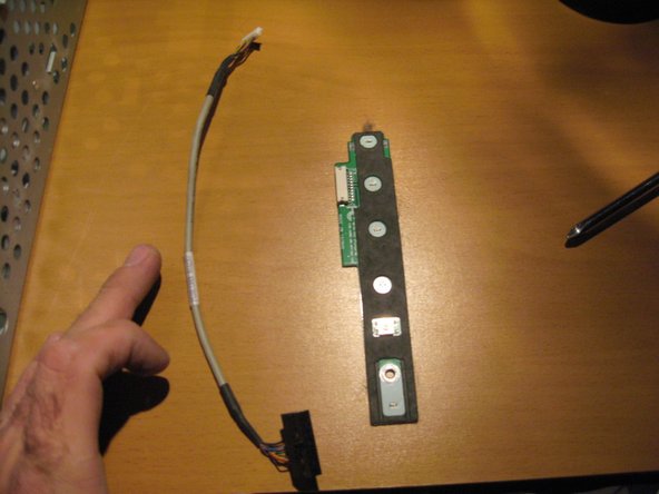
Remove all Connections from Front Panel assembly as shown in image.
-
Unscrew the one screw holding the front panel connectors to the case.
-
Pull Front panel connector assembly out of case
-
On this Panel is an S-Video in, Red, White and Yellow RCA inputs an Ilink S400 port and 2 USB Ports
-
-
-
Dieser Schritt ist noch nicht übersetzt. Hilf mit, ihn zu übersetzen!
-
To remove Floppy drive, Unlatch Retainer and swing Drive outward as shown.
-
-
Dieser Schritt ist noch nicht übersetzt. Hilf mit, ihn zu übersetzen!
-
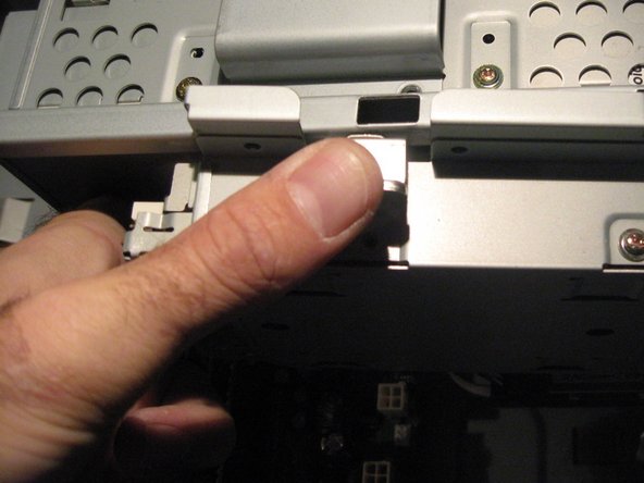
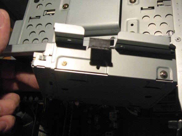
To Remove the top of the case, unclip the retaining clips as marked
-
Pull top from case
-
-
Dieser Schritt ist noch nicht übersetzt. Hilf mit, ihn zu übersetzen!
-
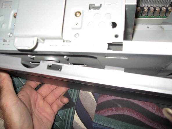
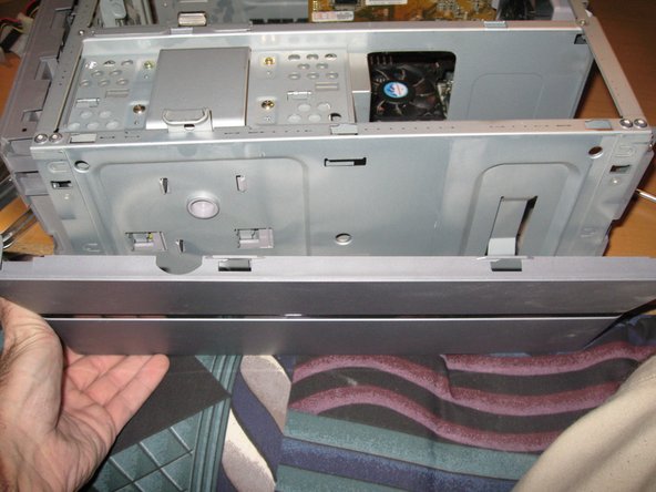
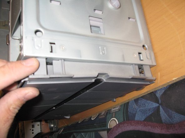
Next to remove the Front Panel of the Case.
-
There are retaining clips as with the top of the case, Unclip them and remove the Front Panel.
-
-
Dieser Schritt ist noch nicht übersetzt. Hilf mit, ihn zu übersetzen!
-
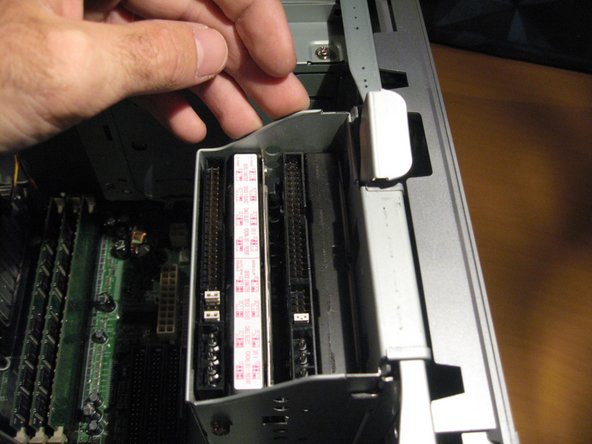
Remove the Sony Memory card reader by unplugging it from the motherboard and unscrewing the single screw (in red). Then simply slide it out of it's little niche
-
Next we will remove both of the Optical Disk Drives.
-
Pull up on latch, releasing the lock enabling you to pull up on drive box assembly and lift out of case
-
-
Dieser Schritt ist noch nicht übersetzt. Hilf mit, ihn zu übersetzen!
-
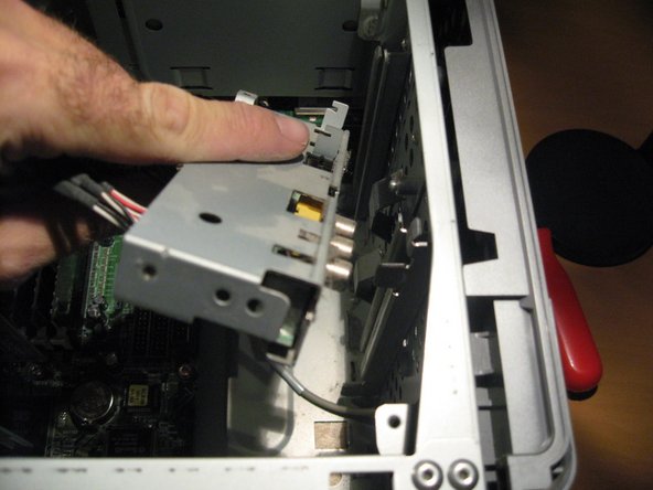
Removing of the Optical Drive Bay.
-
Then a quick look at the interior of the PC So Far
-
Now onto the Power button / Light panel in the front of the PC.
-
-
Dieser Schritt ist noch nicht übersetzt. Hilf mit, ihn zu übersetzen!
-
Unscrew single screw at front of PC to remove . Unattach connector on front side and pull cable through hole in Case.
-
-
Dieser Schritt ist noch nicht übersetzt. Hilf mit, ihn zu übersetzen!
-
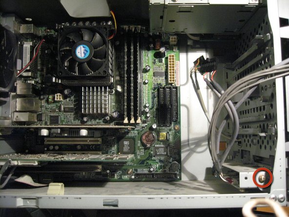
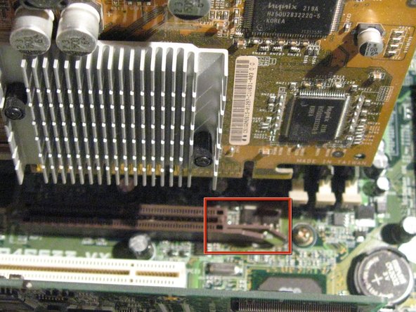
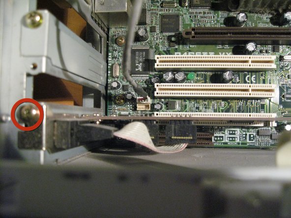
Now we will remove our AGP Graphics card by first removing the screw from the top left holding it secure to the card slot.(in Red)
-
Before pulling the card out of it's placement you must unlatch this little plastic lever to release. (Second image in RED)
-
-
Dieser Schritt ist noch nicht übersetzt. Hilf mit, ihn zu übersetzen!
-
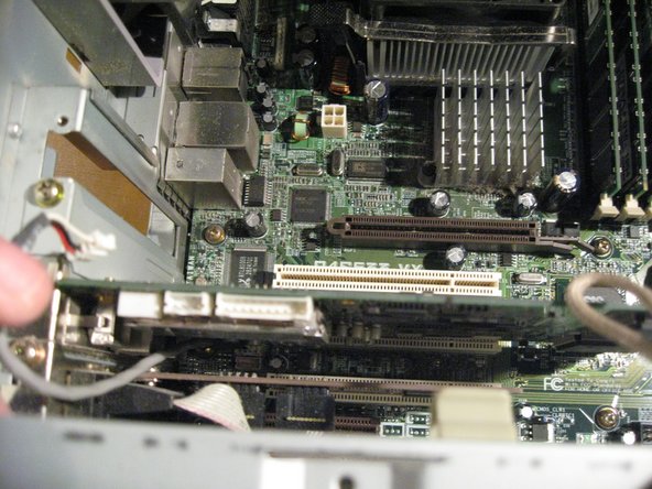
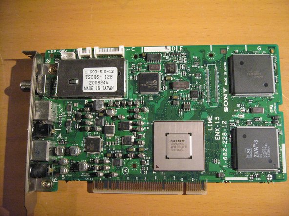
Next is the PCI Mpeg Decoder Board. Remove the Cable that connects from the motherboard to the card.
-
Unscrew and remove the Mpeg/Video In Board.
-
And remove the Last PCI Card by unscrewing the single Screw. This card is a PCI -Serial Port adapter.
-
-
Dieser Schritt ist noch nicht übersetzt. Hilf mit, ihn zu übersetzen!
-
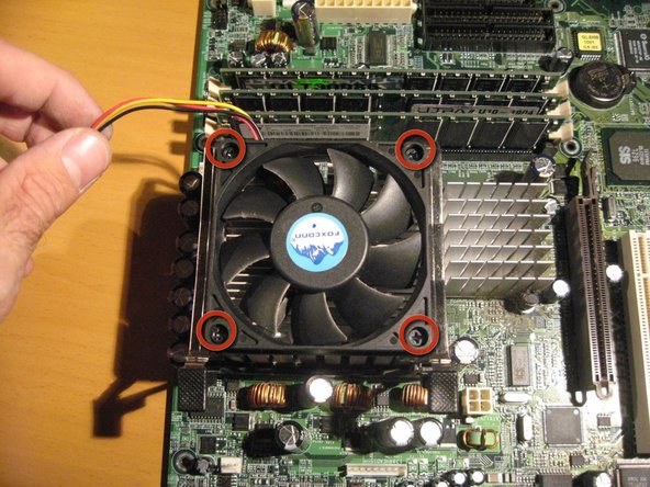
In order to remove the case fan, First disconnect its power cable from the Motherboard.
-
Then unlatch the Four Retaining clips to release the fan- and Remove.
-
-
Dieser Schritt ist noch nicht übersetzt. Hilf mit, ihn zu übersetzen!
-
Now to remove the Motherboard-Remove Labeled Screws in image
-
Be Careful to keap mind of the connection ports on the rear of the Motherboard while removing. So your going to want to lift it out first on the right side then the side with the ports.
-
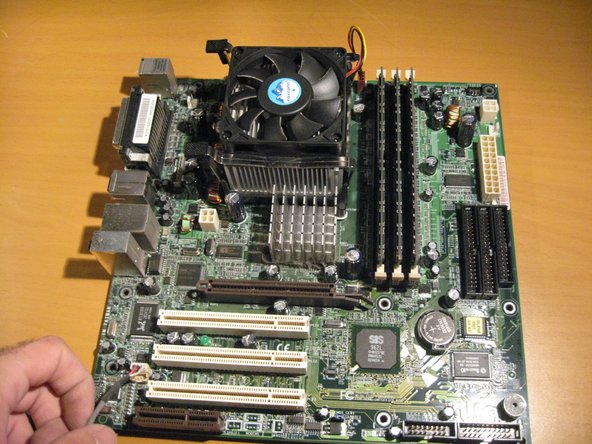
Now lift the Motherboard out of the Case
-
Disconnect the PC fan from the motherboard, Unscrew the four screws and remove.
-
-
Dieser Schritt ist noch nicht übersetzt. Hilf mit, ihn zu übersetzen!
-
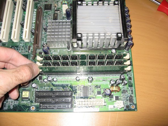
Unlatch the Memory Slots on either side.
-
Remove Memory Dimms by lifting out of slot
-
-
Dieser Schritt ist noch nicht übersetzt. Hilf mit, ihn zu übersetzen!
-
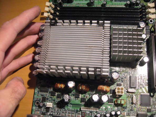
In order to remove heatsink, apply pressure to the far side and pull out of latch on near side (Use Both hands).
-
After Releasing clips lift up and remove heatsink.
-
-
Dieser Schritt ist noch nicht übersetzt. Hilf mit, ihn zu übersetzen!
-
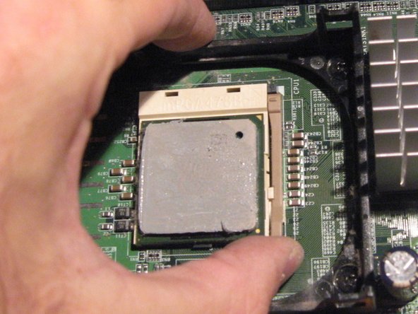
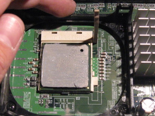
This particular Setup is called a Pin Grid Array (PGA)
-
In order to remove the Processor, lift the light brown latch out and up (as shown)
-
Careful, the top of the processor also has thermal paste on it.
-
-
Dieser Schritt ist noch nicht übersetzt. Hilf mit, ihn zu übersetzen!
-
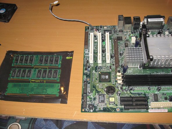
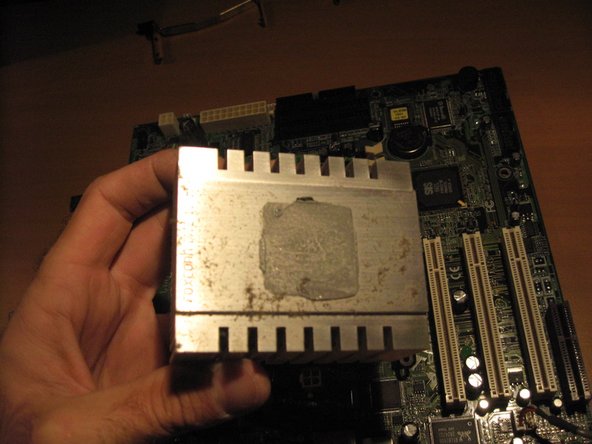
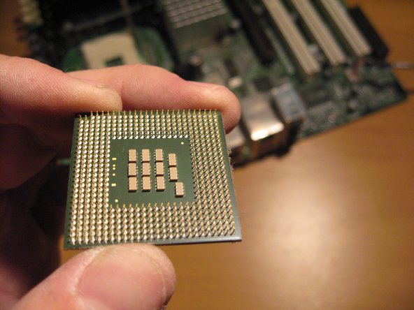
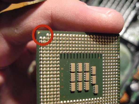
A look at the Processor topside and underside.
-
This Particualr Intel Chip is a 2.53GHZ Pentium 4
-
-
Dieser Schritt ist noch nicht übersetzt. Hilf mit, ihn zu übersetzen!
-
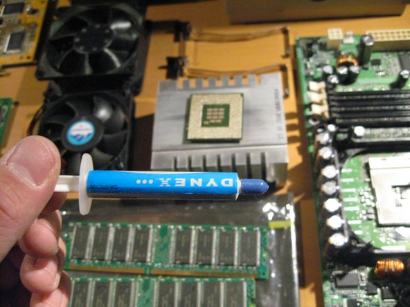
I am going to clean the thermal paste off of the Processor and the heatsink and add a new application. This is not particularly needed but in this case i felt i would.
-


Ein Kommentar
Any videos how to put it all back together now. I took mine apart. Need help putting it back together