Was du brauchst
-
Dieser Schritt ist noch nicht übersetzt. Hilf mit, ihn zu übersetzen!
-
Power off and remove SIM card tray.
-
-
Dieser Schritt ist noch nicht übersetzt. Hilf mit, ihn zu übersetzen!
-
Heat up the back cover to soften the adhesive.
-
Place the suction cup to open a gap from top side, then insert guitar picks and slide it to cut the adhesive underneath.
-
Remove back cover.
-
-
Dieser Schritt ist noch nicht übersetzt. Hilf mit, ihn zu übersetzen!
-
Twist off 10 Phillips screws all.
-
Loosen NFC clip and flashlight clip.
-
-
Dieser Schritt ist noch nicht übersetzt. Hilf mit, ihn zu übersetzen!
-
Remove the plastic bracket.
-
Pry up and remove back frame.
-
-
-
Dieser Schritt ist noch nicht übersetzt. Hilf mit, ihn zu übersetzen!
-
Release charging port connector.
-
Remove plastic protective bar.
-
Pry up motherboard assembly from this side. There are three flex connectors connecting the motherboard underneath. So pry up the motherboard assembly gently.
-
The motherboard may be attached to the case by a sticky pad near the charging connector. This can be dislodged by very carefully rotating the motherboard side to side, checking that the flex connectors aren't being stretched.
-
-
Dieser Schritt ist noch nicht übersetzt. Hilf mit, ihn zu übersetzen!
-
Push audio jack out of the slot, no adhesive underneath.
-
Release LCD flex connector and main flex connector by flipping up the white locking tab of the connector base.
-
Separate motherboard assembly from middle housing.
-
-
Dieser Schritt ist noch nicht übersetzt. Hilf mit, ihn zu übersetzen!
-
Remove audio jack flex by flipping up the white locking tab of the connector base.
-
-
Dieser Schritt ist noch nicht übersetzt. Hilf mit, ihn zu übersetzen!
-
Remove flashlight flex by flipping up the white locking tab of the connector base.
-
-
Dieser Schritt ist noch nicht übersetzt. Hilf mit, ihn zu übersetzen!
-
Remove microphone flex by flipping up the white locking tab of the connector base.
-
-
Dieser Schritt ist noch nicht übersetzt. Hilf mit, ihn zu übersetzen!
-
Take away NFC antenna on battery.
-
-
Dieser Schritt ist noch nicht übersetzt. Hilf mit, ihn zu übersetzen!
-
Release battery connector and pull off adhesive tapes underneath.
-
Pry up and remove battery.
-
-
Dieser Schritt ist noch nicht übersetzt. Hilf mit, ihn zu übersetzen!
-
Loosen adhesive underneath vibration motor.
-
Loosen side button assembly. There is fingerprint scanner here, be careful.
-
Loosen noise canceling microphone.
-
-
Dieser Schritt ist noch nicht übersetzt. Hilf mit, ihn zu übersetzen!
-
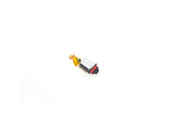
Loosen all adhesive underneath side button flex assembly.
-
Here is side button flex assembly. It’s integrated by vibration motor, side button connector, fingerprint scanner connector and noise-canceling mic.
-
-
Dieser Schritt ist noch nicht übersetzt. Hilf mit, ihn zu übersetzen!
-
The sticker underneath LCD assembly is a little bit strong, so use heat gun to soften it for a few minutes.
-
Remove LCD with digitizer assembly carefully.
-


6 Kommentare
The Rear Camers is what rattles if tapped on the corners.
My Z5 Compact frame is broken near to the power button (the color part).
Is there any way to buy just the frame?
What is the black layer behind the LCD (which can be seen through squares left for SoC heatsinks). Is it a graphite cooling shield just like it is in XZ Premium?