Einleitung
This is a short video on how it should look like when you take it apart
Einführungsvideo
-
-
First take off the back two pieces, you might need something to stick in in order to pop them out
-
-
-
Screw off all the screws, 1 screw is in the middle, and the 4 other screws are in each corner
-
-
-
-
So how does the electricity works;It uses electricity from the batteries. Also how it works; when you press a button it will stop the electricity and transmit inputs into the game
-
-
-
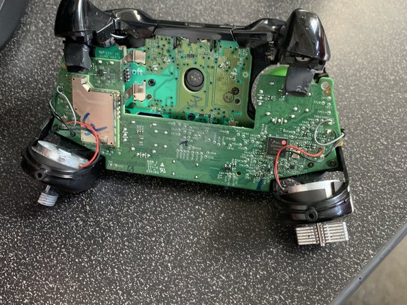
STICKS - The Sticks are the same 10k POT style as previous controllers, but are new and smaller than the 360 versions. They have a 1.8v AN+ that comes from a Regulator (U8) and it's also the vRef for U1 on the MCU board.
-
-
-
The Triggers use Linear Hall Sensors now, U10 (RT) and U11 (LT). They have 3 pins, 1 - VDD (power), 2 - Output, 3 - VSS (ground). The VDD for them comes from U9, which is turned on/off by U1 at 125Hz, 8ms period, On ~1.4ms, Off ~6.6ms (~18% Duty Cycle). This is done mainly to save power.
-
-
-
The Power board has 3 parts U1 is for when the USB cable is attached, it takes the 5v and knocks it down to ~3v for the other two circuits. U2 is for a 3.5v source that powers the LED, IR LEDs and the Rumble motors. It's TP7 on the MCU board. U3 is for the 3.3v source that powers pretty much everything on the MCU board. It's TP9 on the MCU board.
-


Ein Kommentar
A lot of help, thanks. I got an elite 2 so figured if see whats inside my stock boy