Diese Version enthält möglicherweise inkorrekte Änderungen. Wechsle zur letzten geprüften Version.
Was du brauchst
-
-
Bewge den Schieber ganz nach links, bis der Akku herausspringt. Hebe ihn hoch und entferne ihn.
-
-
Dieser Schritt ist noch nicht übersetzt. Hilf mit, ihn zu übersetzen!
-
Remove the RAM port cover by unscrewing the two screws.
-
-
Dieser Schritt ist noch nicht übersetzt. Hilf mit, ihn zu übersetzen!
-
Use a Phillips #00 screwdriver to remove the two screws securing Hard Disk Drive (HDD) cover.
-
-
Dieser Schritt ist noch nicht übersetzt. Hilf mit, ihn zu übersetzen!
-
Use a Phillips #00 screwdriver to remove the 25 screws securing the bottom of the computer.
-
-
Dieser Schritt ist noch nicht übersetzt. Hilf mit, ihn zu übersetzen!
-
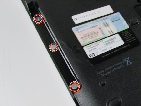
Using the Phillips #0 screwdriver remove the 2 screws.
-
-
Dieser Schritt ist noch nicht übersetzt. Hilf mit, ihn zu übersetzen!
-
Flip over HP Pavilion dv6700 so that the top is facing you.
-
Open up HP Pavilion dv6700.
-
-
Dieser Schritt ist noch nicht übersetzt. Hilf mit, ihn zu übersetzen!
-
Use an iFixit opening tool to pry open the plastic bar above the keyboard.
-
-
Dieser Schritt ist noch nicht übersetzt. Hilf mit, ihn zu übersetzen!
-
Pull out and up on keyboard to remove it.
-
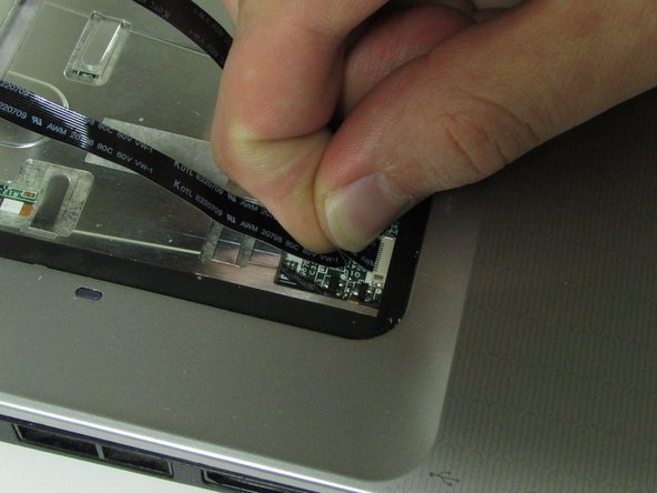
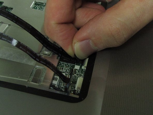
Slide the two black locks on the side of the keyboard cable connection port up to release the cable.
-
Grip the ribbon cable near the connection point and gently but firmly pull it out.
-
-
-
Dieser Schritt ist noch nicht übersetzt. Hilf mit, ihn zu übersetzen!
-
Flip over the plastic bar.
-
Detach the display connector.
-
-
Dieser Schritt ist noch nicht übersetzt. Hilf mit, ihn zu übersetzen!
-
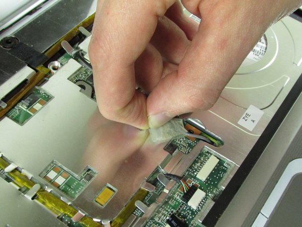
Pull up on tape holding down wires.
-
-
Dieser Schritt ist noch nicht übersetzt. Hilf mit, ihn zu übersetzen!
-
Pull up on the WiFi wires and out from under the metal tabs.
-
-
Dieser Schritt ist noch nicht übersetzt. Hilf mit, ihn zu übersetzen!
-
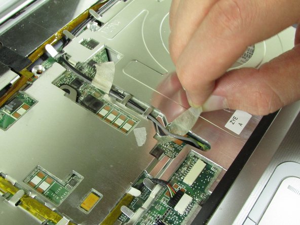
Disconnect the connector from the port.
-
Remove the wire from under the metal tabs.
-
Let wire hang loose after removing under the tabs.
-
-
Dieser Schritt ist noch nicht übersetzt. Hilf mit, ihn zu übersetzen!
-
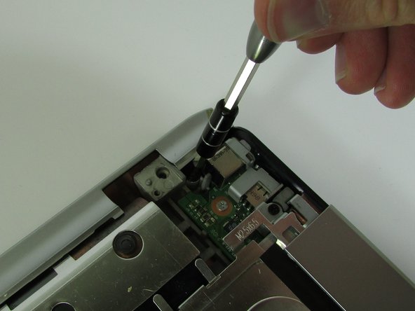
Use a Phillips #00 screwdriver to remove the black screw located in the top right corner near the display.
-
-
Dieser Schritt ist noch nicht übersetzt. Hilf mit, ihn zu übersetzen!
-
Pull upward on the screen connector tab.
-
-
Dieser Schritt ist noch nicht übersetzt. Hilf mit, ihn zu übersetzen!
-
Use a Phillips #00 screwdriver to remove the black screw securing the screen.
-
Lift the screen off and set it aside.
-
-
Dieser Schritt ist noch nicht übersetzt. Hilf mit, ihn zu übersetzen!
-
Unscrew the black screw in the top right corner using the Phillips #00 screwdriver.
-
Pull up on the top piece and remove it.
-
-
Dieser Schritt ist noch nicht übersetzt. Hilf mit, ihn zu übersetzen!
-
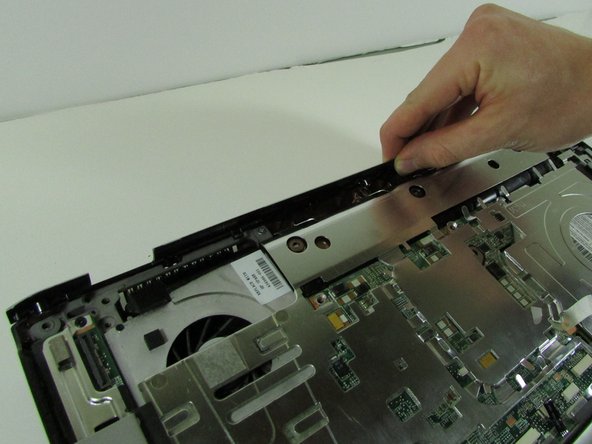
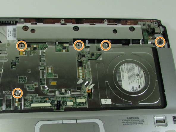
Remove the screw in top left corner using the Phillips #00 screwdriver
-
Remove the five screws that are located on the motherboard cover.
-
Pull up on the cover to remove it.
-
-
Dieser Schritt ist noch nicht übersetzt. Hilf mit, ihn zu übersetzen!
-
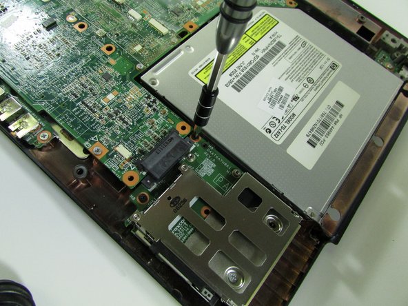
Remove the four screws from the ExpressCard component using the Phillips #00 screwdriver.
-
-
Dieser Schritt ist noch nicht übersetzt. Hilf mit, ihn zu übersetzen!
-
Remove ExpressCard component by sliding it out.
-
Remove Optical Drive by sliding it out.
-
-
Dieser Schritt ist noch nicht übersetzt. Hilf mit, ihn zu übersetzen!
-
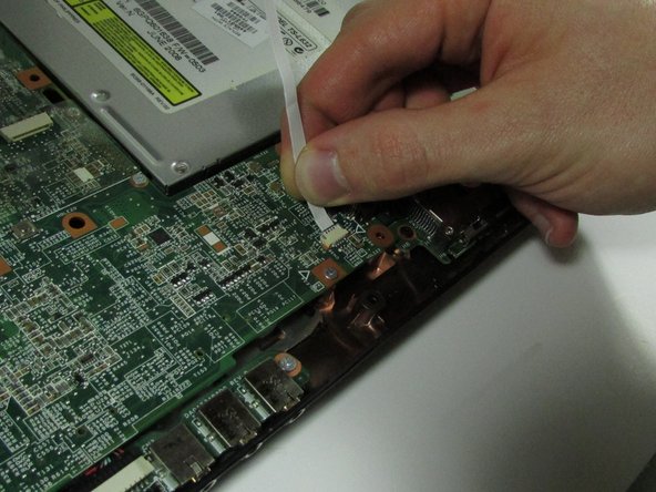
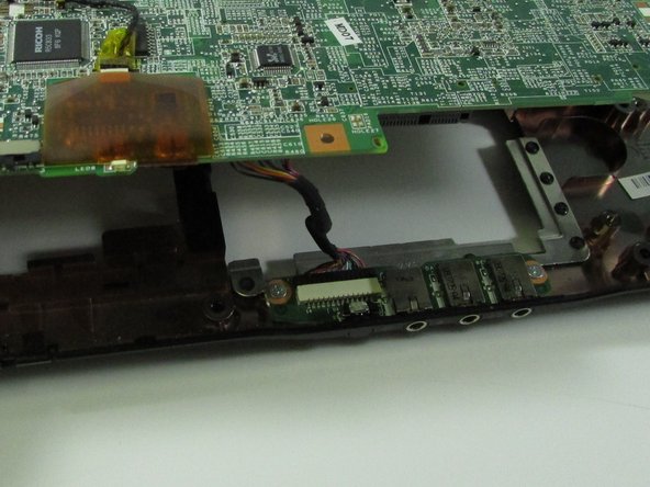
Detach connector from the motherboard.
-
-
Dieser Schritt ist noch nicht übersetzt. Hilf mit, ihn zu übersetzen!
-
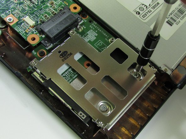
Using the Phillips #00 screwdriver, remove the one screw near where the ExpressCard component was.
-
-
Dieser Schritt ist noch nicht übersetzt. Hilf mit, ihn zu übersetzen!
-
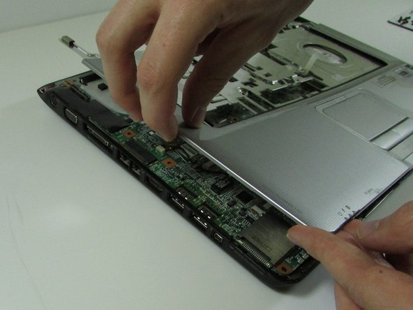
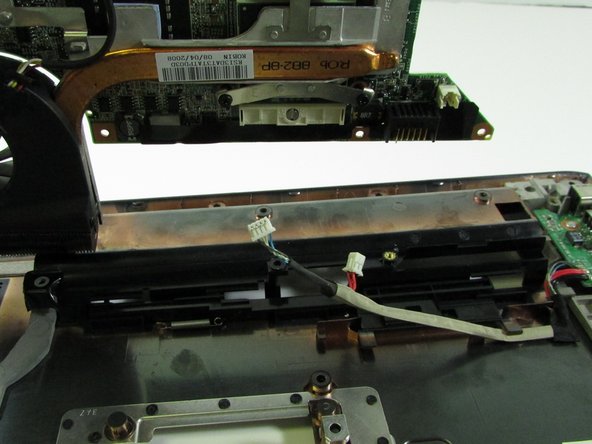
Lift up motherboard.
-
Detach the motherboard connector at the front under the motherboard.
-
-
Dieser Schritt ist noch nicht übersetzt. Hilf mit, ihn zu übersetzen!
-
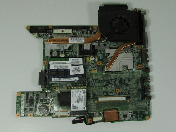
Lift up and out the motherboard.
-
Detach the connector under the motherboard.
-
Remove the motherboard.
-
-
Dieser Schritt ist noch nicht übersetzt. Hilf mit, ihn zu übersetzen!
-
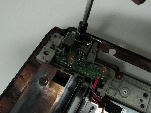
Remove the screws securing the charging port.
-


Rückgängig: Ich habe diese Anleitung nicht absolviert.
4 weitere Nutzer:innen haben diese Anleitung absolviert.
Team

University of Illinois Urbana-Champaign, Team 1-118, Wolske Fall 2015 Mitglied von University of Illinois Urbana-Champaign, Team 1-118, Wolske Fall 2015
UICU-WOLSKE-F15S1G118
1 Mitglied
6 Anleitungen geschrieben