Einleitung
This guide will show you how to replace the HTC Vive's individual lens and OLED assemblies. Each assembly includes the lenses, lens housing, and OLED screen.
Was du brauchst
-
-
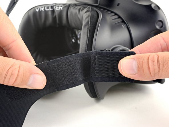
Pull the hook-and-loop (Velcro) closure at the top of the head strap apart to release the top of the head strap.
-
-
-
Slide the top part of the head strap through its metal loop on the headset to remove it.
-
-
-
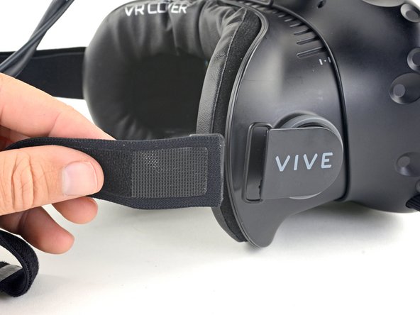
Pull the hook-and-loop closure at the right side of the head strap apart to release the right side of the head strap.
-
Slide the right side of the head strap through its metal loop to remove it.
-
-
-
Pull the hook-and-loop closure at the left side of the head strap apart to release the left side of the head strap.
-
Slide the left side of the head strap through its metal loop to remove it.
-
-
-
Slide the head strap along the cable, away from the Vive.
-
When the head strap comes to the end of the cable, gently slide it over the plugs and remove it.
-
-
-
Use a T5 Torx driver to remove the two 12 mm-long screws securing the head strap mounts on either side of the headset.
-
-
-
Slide the facerest straight away from the headset to remove it.
-
-
-
Use tweezers to remove the small stickers over the four screws securing the outer shell.
-
Use a T5 Torx driver to remove the four 3.4 mm-long screws securing the outer shell.
-
-
-
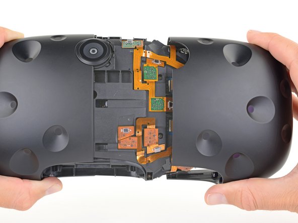
Use the flat end of a spudger to pry up the top edge of the right half of the outer shell, behind the component cover and near the seam in the center, until it is unclipped from the headset.
-
-
-
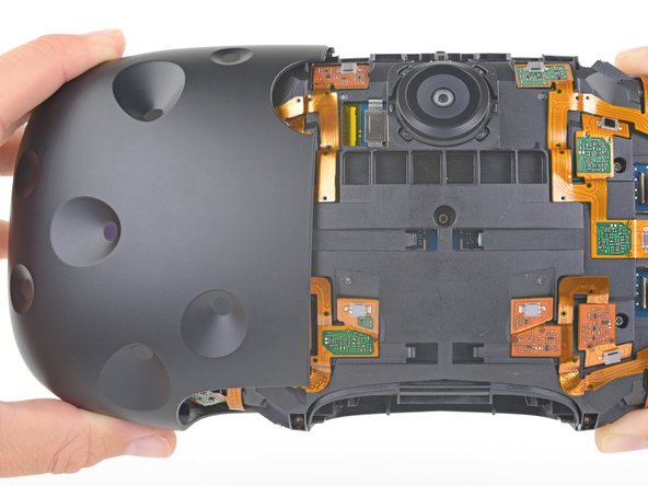
Grasp the right half the outer shell and pull it to the right and toward the front of the headset until you feel the clips on the front of the cover release.
-
If the shell is difficult to remove, try prying along the seam with the flat end of a spudger to release the clips.
-
-
-
-
Repeat the last three steps for the left side of the outer shell and remove it.
-
-
-
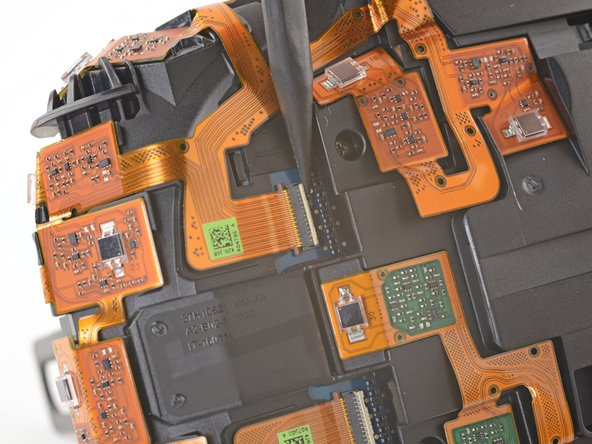
Use tweezers to remove the clear tape over all four of the sensor array cable connectors.
-
-
-
Use the pointed end of a spudger to flip up the small locking flap on one of the sensor array ZIF connectors.
-
Slide the cable straight out of its socket on the motherboard.
-
-
-
Repeat the previous step for the remaining three sensor array cables to disconnect the remaining cables.
-
-
-
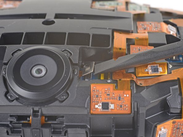
Use the flat end of a spudger to pry the camera cable connector straight up from its socket on the motherboard.
-
-
-
Use a PH000 driver to remove the five 3.9 mm screws securing the sensor array.
-
-
-
Use a PH000 driver to remove the four 3.9 mm screws securing the sensor array.
-
-
-
Use a PH000 driver to remove the four 3.9 mm screws securing the sensor array.
-
-
-
Lift the sensor array away from the headset to remove it.
-
-
-
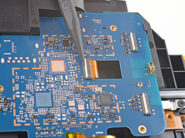
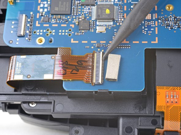
Remove the tape covering the interconnect cable socket.
-
Use the point of a spudger to flip up the small locking flap on the cable socket.
-
Slide the interconnect cable straight out of its socket on the motherboard.
-
-
-
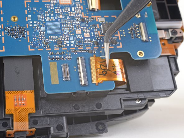
Remove the tape covering the left OLED cable socket.
-
Use the point of a spudger to flip up the small locking flap on the cable socket.
-
Slide the left OLED cable straight out of its socket on the motherboard.
-
-
-
Remove the tape covering the right OLED cable socket.
-
Use the point of a spudger to flip up the small locking flap on the cable socket.
-
Slide the right OLED cable straight out of its socket on the motherboard.
-
-
-
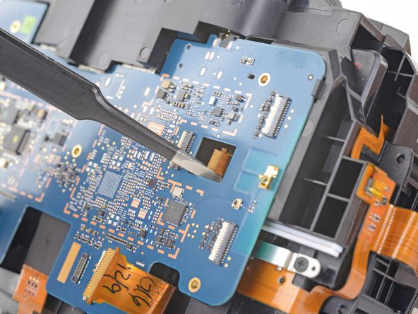
Use a pair tweezers to slightly twist the interconnect cable and press it down until the tabs on either side of the cable clear the hole in the motherboard.
-
-
-
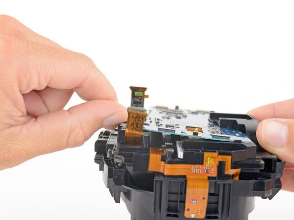
Press the non-port-end of the motherboard toward the top of headset while hinging it away from the midframe to free it from the clips securing that end.
-
Slide the motherboard toward the bottom of the headset, over the clips, to remove it.
-
-
-
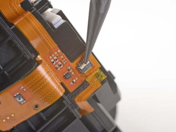
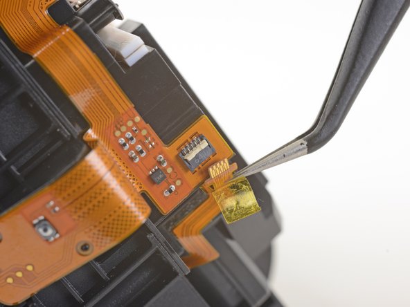
Use a pair of tweezers to peel back the plastic covering the eyepiece midframe cable socket.
-
Use the pointed end of a spudger to flip up the plastic locking flap on the socket.
-
Slide the cable straight out of its socket to remove it.
-
-
-
Use a PH000 driver to remove the four 3.9 mm screws securing the facerest midframe.
-
-
-
Lift the facerest midframe off of the eyepiece midframe.
-
-
-
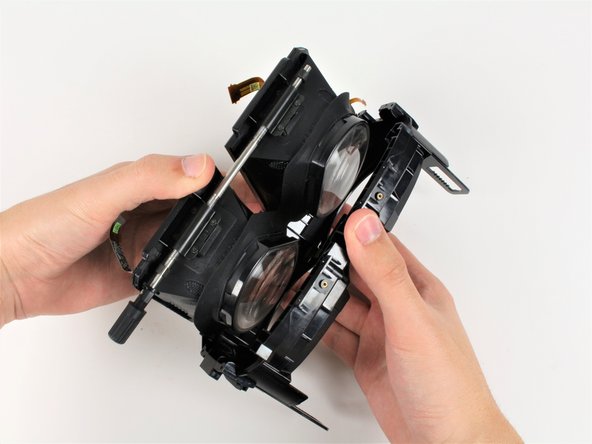
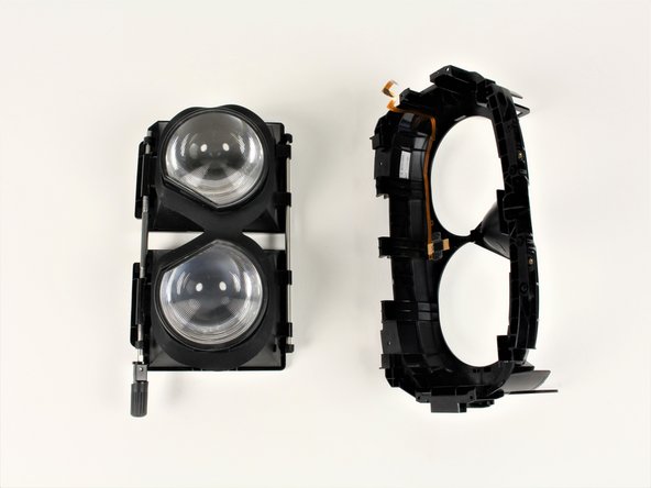
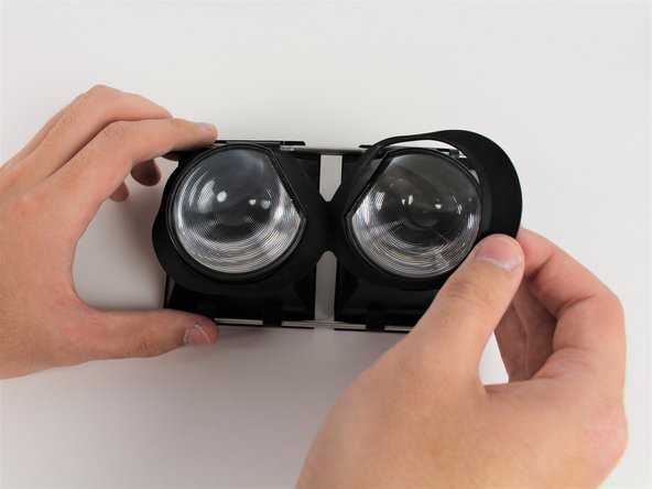
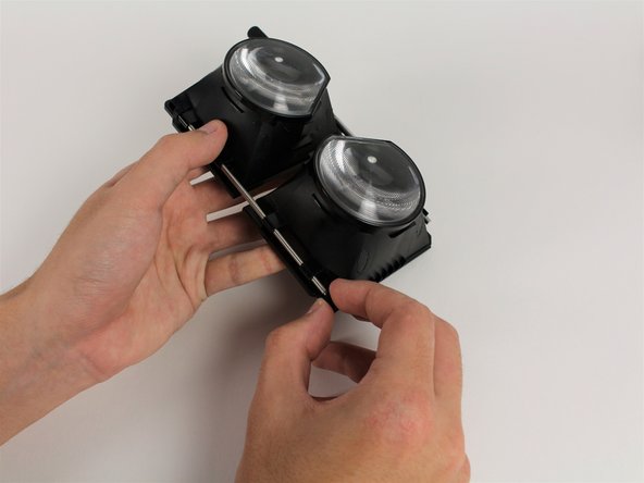
Pivot the bottom rod attached to the eyepieces outwards from the facerest to free the eyepieces.
-
Pull facerest from the eyepieces to separate the parts.
-
-
-
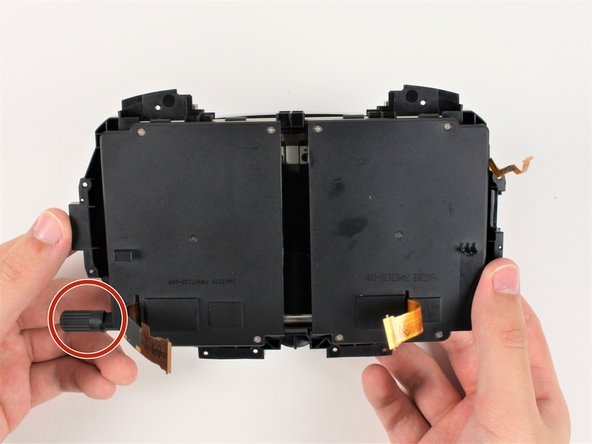
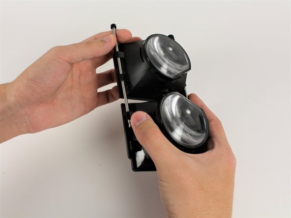
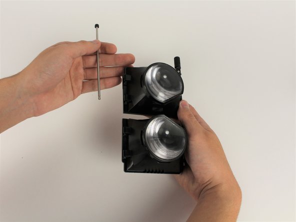
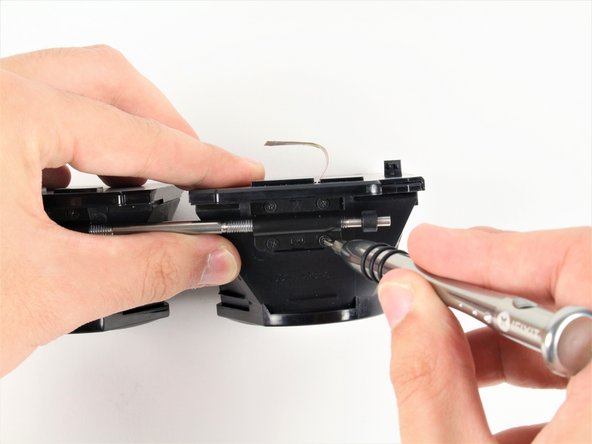
Pull one of the rubber ends off the top rod.
-
Pulling from the other end of the rod, slide the top rod out.
-
-
-
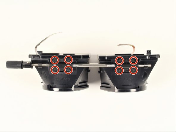
Remove the four 3mm #00 Philips screws from each eyepiece, removing eight screws total.
-


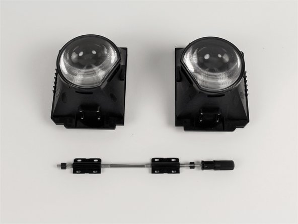
To reassemble your device, follow these instructions in reverse order.
To reassemble your device, follow these instructions in reverse order.
Rückgängig: Ich habe diese Anleitung nicht absolviert.
2 weitere Nutzer:innen haben diese Anleitung absolviert.
Team

Cal Poly, Team S18-G1, Forte Fall 2017 Mitglied von Cal Poly, Team S18-G1, Forte Fall 2017
CPSU-FORTE-F17S18G1
5 Mitglieder
11 Anleitungen geschrieben