Diese Version enthält möglicherweise inkorrekte Änderungen. Wechsle zur letzten geprüften Version.
Was du brauchst
-
Dieser Schritt ist noch nicht übersetzt. Hilf mit, ihn zu übersetzen!
-
Flip the hoverboard so the bottom is facing up.
-
-
Dieser Schritt ist noch nicht übersetzt. Hilf mit, ihn zu übersetzen!
-
Using a Phillips #1 screwdriver, remove the two 14 mm screws located closest to the center of the hoverboard.
-
Using a Phillips #1 screwdriver, remove the four 12 mm screws located in the middle of the panel.
-
Using a Phillips #1 screwdriver, remove two 15 mm screws located closest to the wheel.
-
-
Dieser Schritt ist noch nicht übersetzt. Hilf mit, ihn zu übersetzen!
-
Grip the bottom left panel and lift up to remove.
-
-
Dieser Schritt ist noch nicht übersetzt. Hilf mit, ihn zu übersetzen!
-
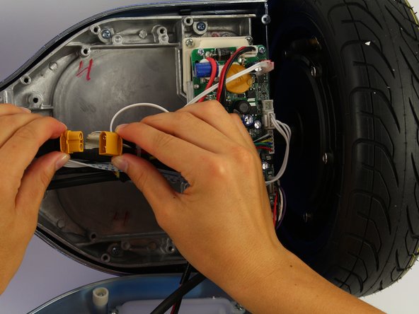
Unplug the battery from the gyroscope by holding the yellow connector and pulling apart.
-
-
-
Dieser Schritt ist noch nicht übersetzt. Hilf mit, ihn zu übersetzen!
-
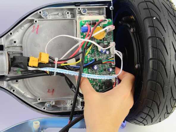
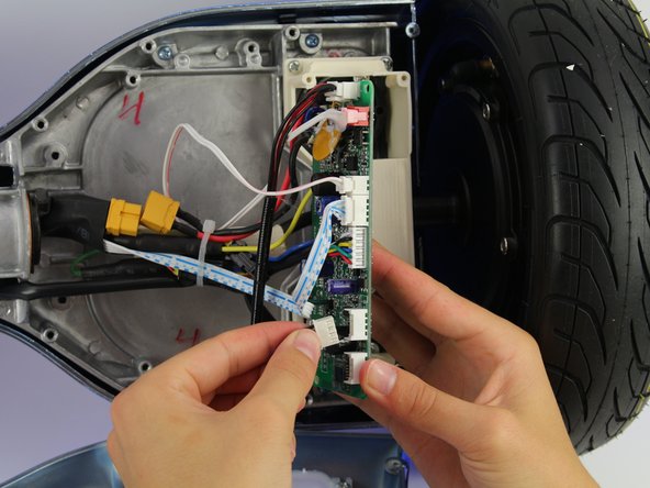
Remove four 12 mm Phillips #1 head screws from the corners of the green gyroscope/motherboard.
-
-
Dieser Schritt ist noch nicht übersetzt. Hilf mit, ihn zu übersetzen!
-
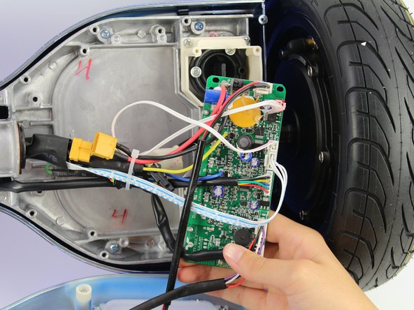
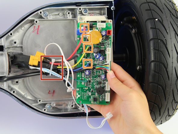
Unplug the bottom right connector by squeezing it and pulling it away from the board.
-
-
Dieser Schritt ist noch nicht übersetzt. Hilf mit, ihn zu übersetzen!
-
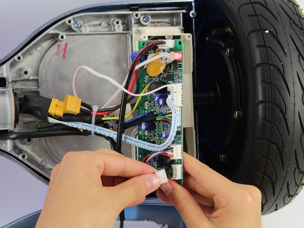
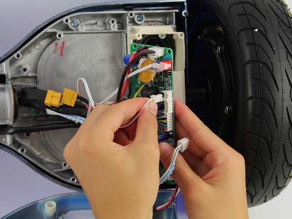
Unplug the light connector by squeezing it and pulling away from the board.
-
-
Dieser Schritt ist noch nicht übersetzt. Hilf mit, ihn zu übersetzen!
-
Unplug the blue and white wires by squeezing the connector and pulling away from the board.
-
-
Dieser Schritt ist noch nicht übersetzt. Hilf mit, ihn zu übersetzen!
-
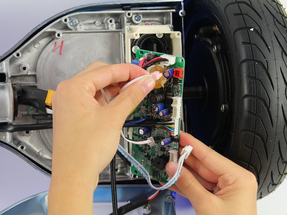
Unplug the small white connector by squeezing it and pulling away from the board.
-
-
Dieser Schritt ist noch nicht übersetzt. Hilf mit, ihn zu übersetzen!
-
Unplug the plug in the red connector.
-
-
Dieser Schritt ist noch nicht übersetzt. Hilf mit, ihn zu übersetzen!
-
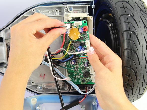
Unplug the charging cable connector by squeezing it and pulling it away from the board.
-
-
Dieser Schritt ist noch nicht übersetzt. Hilf mit, ihn zu übersetzen!
-
Cut the cable tie.
-
Unplug the remaining wires.
-


Team

Cal Poly, Team S15-G4, White Fall 2018 Mitglied von Cal Poly, Team S15-G4, White Fall 2018
CPSU-WHITE-F18S15G4
4 Mitglieder
10 Anleitungen geschrieben