Was du brauchst
-
-
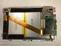
Position the tablet with the top edge by the camera facing down.
-
Insert the plastic opening tool between the front panel and back case at the upper left hand corner of the tablet.
-
-
-
Slide the plastic opening tool along the edge of the tablet between the front panel and back case.
-
Repeat this process for the two shorter edges of the tablet leaving the top edge by the camera still snapped in place.
-
-
-
Using an unfolding motion along the top edge of the tablet, carefully separate the front panel from the back case.
-
-
-
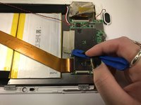
Using the plastic opening tool, lift up the black retaining flap that secures the camera ZIF (zero insertion force) ribbon connector to the motherboard
-
-
-
Pull the ZIF (zero insertion force) ribbon connector out from underneath the black retaining flap.
-
-
-
Using the plastic opening tool, lift up the black retaining flap that secures the ZIF (zero insertion force) ribbon connector over the battery to the motherboard.
-
-
-
-
Pull the ZIF (zero insertion force) ribbon connector out from underneath the black retaining flap.
-
-
-
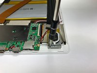
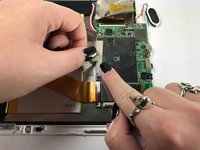
Using the plastic opening tool, lift up the black retaining flap that secures the volume and power button ZIF (zero insertion force) ribbon connector to the motherboard.
-
-
-
Pull the ZIF (zero insertion force) ribbon connector out from underneath the black retaining flap.
-
-
-
Using the Phillips #000 screw driver, unscrew the two 4 mm screws securing the right speaker to the front panel in a counterclockwise direction.
-
-
-
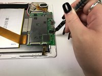
Using the plastic opening tool, remove the silver tape covering the display ZIF (zero insertion force) ribbon connector.
-
-
-
Using the plastic opening tool, lift up the black retaining flap that secures the display ZIF (zero insertion force) ribbon connector to the motherboard.
-
-
-
Pull the ZIF (zero insertion force) ribbon connector out from underneath the black retaining flap.
-
-
-
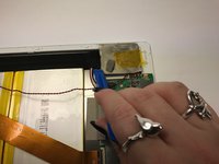
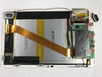
Desolder the four joints connecting the red and black wires from the speakers to the motherboard.
-
-
-
Desolder the three joints connecting the red, black, and white wires from the battery to the motherboard.
-
-
-
Using the plastic opening tool, remove the silver tape that secures the motherboard to the front panel.
-
-
-
Using the Phillips #000 screw driver, unscrew the three 4 mm screws securing the motherboard to the front panel in a counterclockwise direction.
-


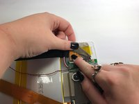


The motherboard is now free from the device and can now be replaced. To reassemble your device, follow these instructions in reverse order.
The motherboard is now free from the device and can now be replaced. To reassemble your device, follow these instructions in reverse order.
Rückgängig: Ich habe diese Anleitung nicht absolviert.
3 weitere Personen haben diese Anleitung absolviert.
Team

Baylor, Team 5-8, Williams Fall 2016 Mitglied von Baylor, Team 5-8, Williams Fall 2016
BU-WILLIAMS-F16S5G8
3 Mitglieder
12 Anleitungen geschrieben