Diese Version enthält möglicherweise inkorrekte Änderungen. Wechsle zur letzten geprüften Version.
Was du brauchst
-
Dieser Schritt ist noch nicht übersetzt. Hilf mit, ihn zu übersetzen!
-
Slide switch to open lock position.
-
-
Dieser Schritt ist noch nicht übersetzt. Hilf mit, ihn zu übersetzen!
-
Press down on the battery cover and slide outwards to open.
-
-
Dieser Schritt ist noch nicht übersetzt. Hilf mit, ihn zu übersetzen!
-
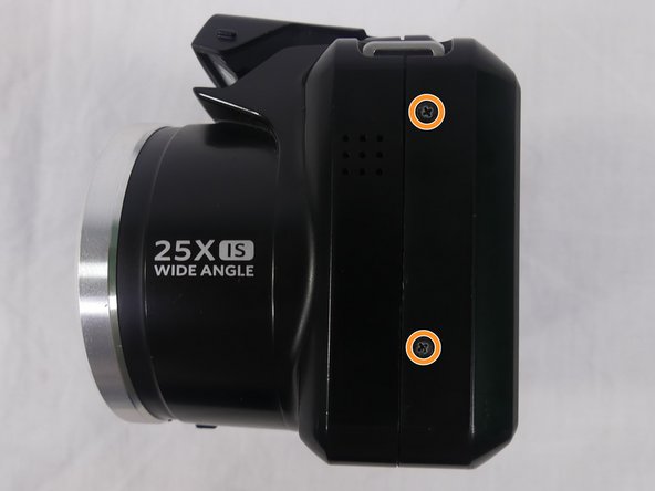
Remove a total of four 5mm JIS #000 screws from around the camera:
-
Two screws from the right side.
-
Two screws from the left side.
-
-
Dieser Schritt ist noch nicht übersetzt. Hilf mit, ihn zu übersetzen!
-
Remove the single 5mm Phillips #00 screw from the bottom.
-
-
Dieser Schritt ist noch nicht übersetzt. Hilf mit, ihn zu übersetzen!
-
Open the flash module.
-
Remove the two 6mm JIS #00 screws found inside of the flash housing.
-
-
-
Dieser Schritt ist noch nicht übersetzt. Hilf mit, ihn zu übersetzen!
-
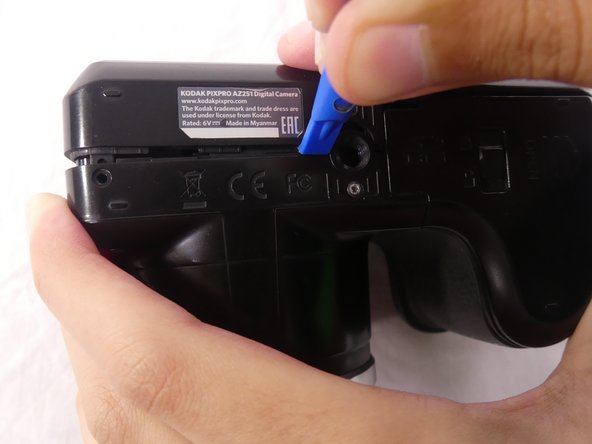
Use a plastic opening tool to pry apart both halves of the camera.
-
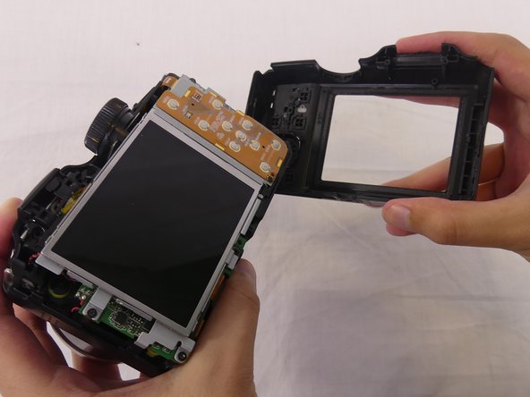
Remove the back panel.
-
-
Dieser Schritt ist noch nicht übersetzt. Hilf mit, ihn zu übersetzen!
-
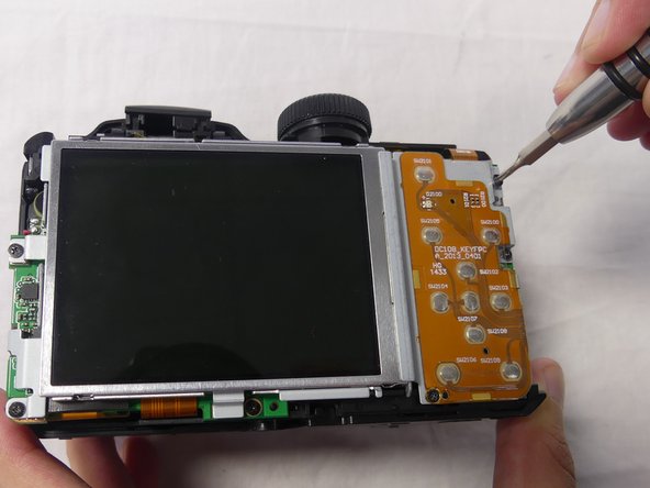
Remove these three JIS #000 screws from the control board:
-
5mm screw.
-
4mm screw.
-
2mm screw.
-
-
Dieser Schritt ist noch nicht übersetzt. Hilf mit, ihn zu übersetzen!
-
Pull the small metal switch plate to the side.
-
-
Dieser Schritt ist noch nicht übersetzt. Hilf mit, ihn zu übersetzen!
-
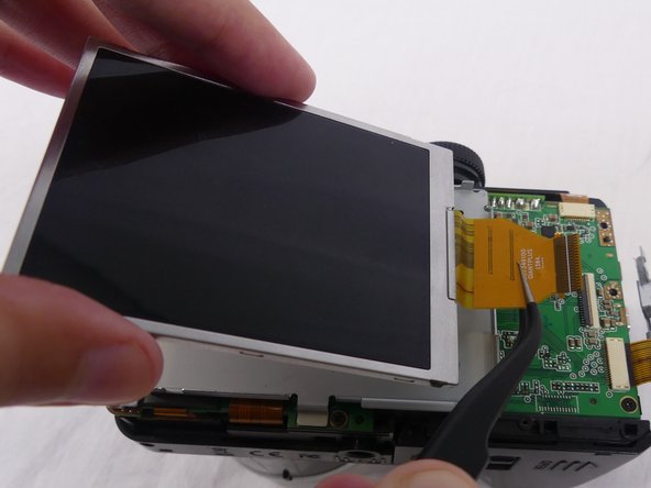
Pry the LCD screen out of the metal housing plate with a plastic opening tool.
-
-
Dieser Schritt ist noch nicht übersetzt. Hilf mit, ihn zu übersetzen!
-
Use a spudger to flip up the retaining flap on the display ribbon cable ZIF socket.
-
Pull the orange cable out of the socket.
-
-
Dieser Schritt ist noch nicht übersetzt. Hilf mit, ihn zu übersetzen!
-
Remove one 4-mm screw using a J000 screwdriver from the top of the camera, near the mode dial.
-
-
Dieser Schritt ist noch nicht übersetzt. Hilf mit, ihn zu übersetzen!
-
Using the tweezers, disconnect the orange cable connection at the top of the motherboard near the mode dial.
-
-
Dieser Schritt ist noch nicht übersetzt. Hilf mit, ihn zu übersetzen!
-
Pull the top side cover up.
-
Rotate the top side cover to the right.
-
-
Dieser Schritt ist noch nicht übersetzt. Hilf mit, ihn zu übersetzen!
-
Turn the camera upside down.
-
Remove two 2mm JIS #000 screws from the metal base of the mode dial.
-
-
Dieser Schritt ist noch nicht übersetzt. Hilf mit, ihn zu übersetzen!
-
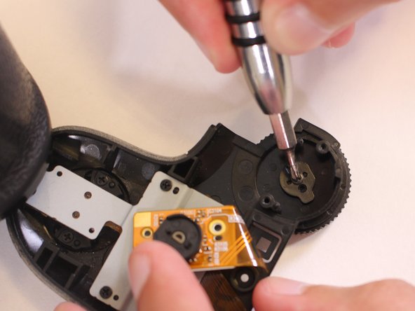
Lift the metal base and remove the 4mm JIS #000 screw from the center of the mode dial.
-
-
Dieser Schritt ist noch nicht übersetzt. Hilf mit, ihn zu übersetzen!
-
The mode dial should now be loose and can be easily removed from the top side cover.
-
Turn the mode dial upside down to remove the metal part inside.
-


Rückgängig: Ich habe diese Anleitung nicht absolviert.
Ein:e weitere:r Nutzer:in hat diese Anleitung absolviert.

Team

USF Tampa, Team S1-G1, Cagle Spring 2018 Mitglied von USF Tampa, Team S1-G1, Cagle Spring 2018
USFT-CAGLE-S18S1G1
4 Mitglieder
7 Anleitungen geschrieben