Diese Version enthält möglicherweise inkorrekte Änderungen. Wechsle zur letzten geprüften Version.
Was du brauchst
-
Dieser Schritt ist noch nicht übersetzt. Hilf mit, ihn zu übersetzen!
-
On the back of the phone, place your thumb on the three raised bumps and slide the back cover upward.
-
-
Dieser Schritt ist noch nicht übersetzt. Hilf mit, ihn zu übersetzen!
-
Remove the two screw covers at the top of phone with tweezers.
-
-
Dieser Schritt ist noch nicht übersetzt. Hilf mit, ihn zu übersetzen!
-
Remove the six Phillips #000 (3mm) screws.
-
-
Dieser Schritt ist noch nicht übersetzt. Hilf mit, ihn zu übersetzen!
-
Use the plastic opening tool to pry the back cover off. Insert the tool between the back cover and red mid section and go around the entire phone.
-
-
Dieser Schritt ist noch nicht übersetzt. Hilf mit, ihn zu übersetzen!
-
Use the tweezers to remove the red and black wires connecting the speaker to the green motherboard by pinching the sides of the plastic base near the motherboard.
-
Set the back cover with the speaker aside.
-
-
-
Dieser Schritt ist noch nicht übersetzt. Hilf mit, ihn zu übersetzen!
-
Use the plastic opening tool to gently lift the snapped-in motherboard from the front panel.
-
-
Dieser Schritt ist noch nicht übersetzt. Hilf mit, ihn zu übersetzen!
-
Gently remove the blue transparent tape from the connector.
-
-
Dieser Schritt ist noch nicht übersetzt. Hilf mit, ihn zu übersetzen!
-
With the plastic opening tool, gently pry the LCD connector from the motherboard.
-
Set the motherboard aside.
-
-
Dieser Schritt ist noch nicht übersetzt. Hilf mit, ihn zu übersetzen!
-
Take the front case and unscrew the four Phillips #000 (1mm) screws around the ribbon.
-
-
Dieser Schritt ist noch nicht übersetzt. Hilf mit, ihn zu übersetzen!
-
Gently pull the orange ribbon from the number pad casing.
-
Set the number pad case to the side once it is detached from the ribbon.
-
-
Dieser Schritt ist noch nicht übersetzt. Hilf mit, ihn zu übersetzen!
-
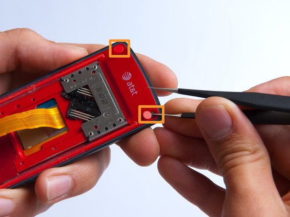
Remove the two red sticker screw coverings at the top corners with tweezers.
-
-
Dieser Schritt ist noch nicht übersetzt. Hilf mit, ihn zu übersetzen!
-
Unscrew the four Phillips #000 (3mm) screws at the corners of the phone.
-
-
Dieser Schritt ist noch nicht übersetzt. Hilf mit, ihn zu übersetzen!
-
Pry the red sliding backing from the front cover by inserting the plastic opening tool in between the two sections and going around the entire phone.
-
Set the red sliding backing and front cover to the side.
-
-
Dieser Schritt ist noch nicht übersetzt. Hilf mit, ihn zu übersetzen!
-
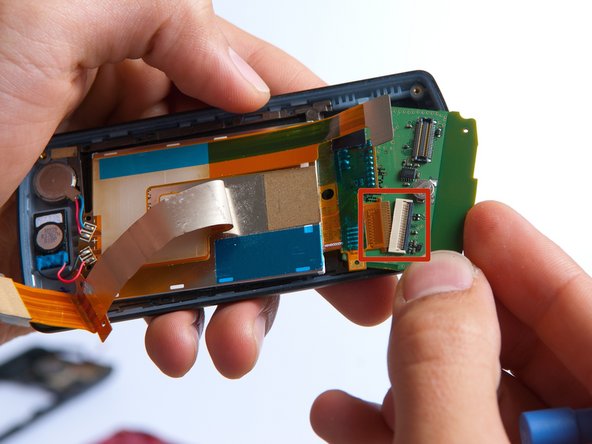
Use a plastic opening tool to carefully disconnect the silver L-shaped LCD screen ribbon.
-
-
Dieser Schritt ist noch nicht übersetzt. Hilf mit, ihn zu übersetzen!
-
Use tweezers to carefully pry up the black retainer on the connector.
-
-
Dieser Schritt ist noch nicht übersetzt. Hilf mit, ihn zu übersetzen!
-
Lift the keypad board away from the phone casing using a plastic opening tool.
-
Slowly rotate the keypad board towards you to disconnect the second orange LCD screen ribbon and remove the board.
-
-
Dieser Schritt ist noch nicht übersetzt. Hilf mit, ihn zu übersetzen!
-
Use a soldering iron and a solder wick to de-solder the 4 wires connected to the LCD screen.
-
The LCD screen can easily be removed at this point by lifting it from the phone casing.
-


Rückgängig: Ich habe diese Anleitung nicht absolviert.
2 weitere Nutzer:innen haben diese Anleitung absolviert.
Team

Cal Poly, Team 4-27, Amido Fall 2013 Mitglied von Cal Poly, Team 4-27, Amido Fall 2013
CPSU-AMIDO-F13S4G27
4 Mitglieder
19 Anleitungen geschrieben