Diese Version enthält möglicherweise inkorrekte Änderungen. Wechsle zur letzten geprüften Version.
Was du brauchst
-
Dieser Schritt ist noch nicht übersetzt. Hilf mit, ihn zu übersetzen!
-
Remove the back cover by firmly pressing against the indent on the back panel. Slide the cover downward and off the phone.
-
-
Dieser Schritt ist noch nicht übersetzt. Hilf mit, ihn zu übersetzen!
-
Remove the battery by placing your fingernail or an opening tool at the bottom edge of the battery and lift it out.
-
-
Dieser Schritt ist noch nicht übersetzt. Hilf mit, ihn zu übersetzen!
-
Remove the two 3.5 mm screws above the battery port with a Phillips #00 screwdriver.
-
-
Dieser Schritt ist noch nicht übersetzt. Hilf mit, ihn zu übersetzen!
-
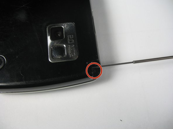
Pull out the antenna to reveal a third screw.
-
Remove the 3.5 mm screw with a Phillips #00 screwdriver.
-
-
-
Dieser Schritt ist noch nicht übersetzt. Hilf mit, ihn zu übersetzen!
-
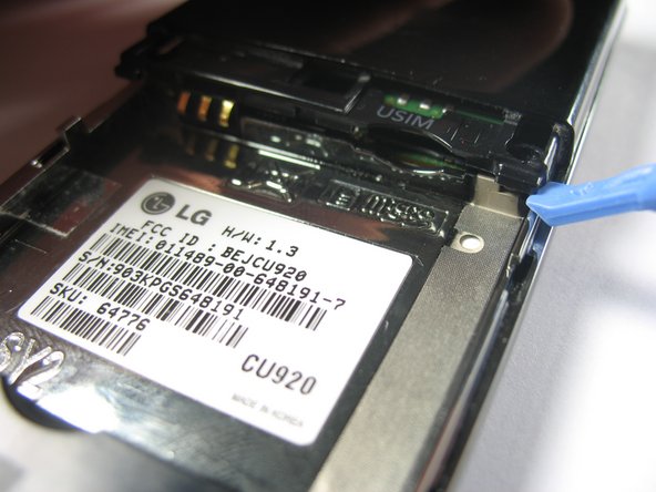
Using a plastic opening tool, gently pop up the plastic tab.
-
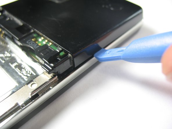
Use the plastic opening tool to pry up the edges of the plastic casing. You will then be able to slide it around the edge to dislodge it.
-
-
Dieser Schritt ist noch nicht übersetzt. Hilf mit, ihn zu übersetzen!
-
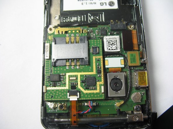
Remove the plastic case to reveal the motherboard.
-
-
Dieser Schritt ist noch nicht übersetzt. Hilf mit, ihn zu übersetzen!
-
Use a spudger to disconnect the cables from the motherboard.
-
-
Dieser Schritt ist noch nicht übersetzt. Hilf mit, ihn zu übersetzen!
-
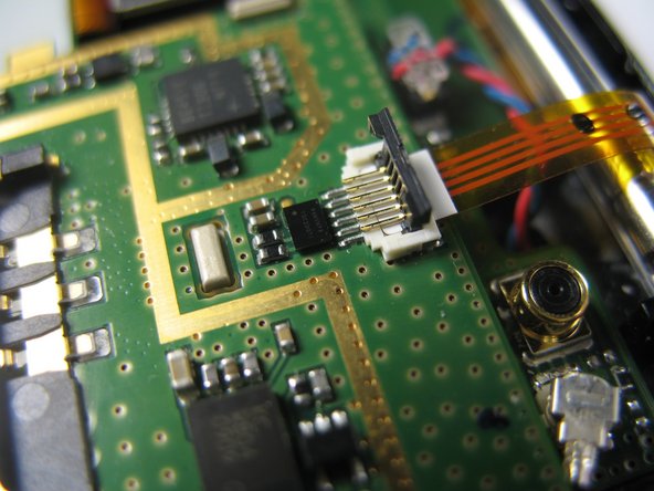
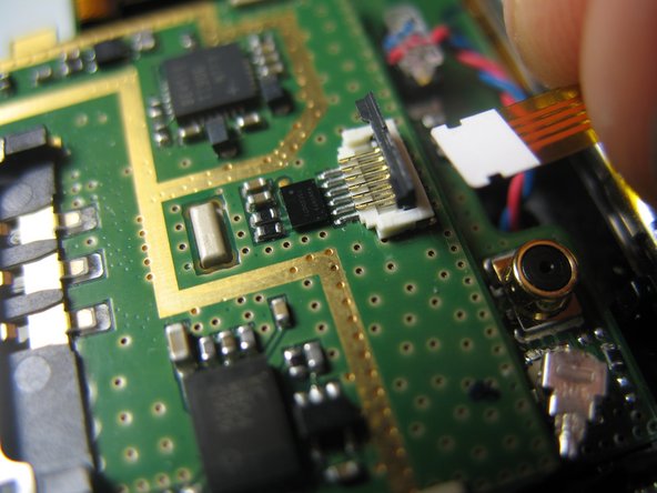
Gently lift the ZIF connector (black tab) holding the ribbon cable in place. When it is in the upright position, remove the cable from the back side.
-
-
Dieser Schritt ist noch nicht übersetzt. Hilf mit, ihn zu übersetzen!
-
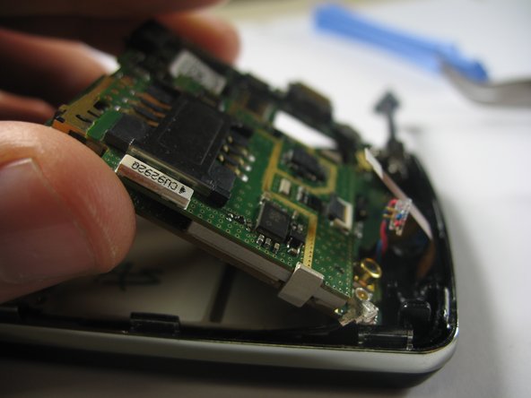
Remove the jack attached to the red and blue wires by carefully pulling it upward from the motherboard.
-
-
Dieser Schritt ist noch nicht übersetzt. Hilf mit, ihn zu übersetzen!
-
Remove the round jack connected to the black cabel by carefully prying it up from beneath with a spudger or plastic opening tool.
-
-
Dieser Schritt ist noch nicht übersetzt. Hilf mit, ihn zu übersetzen!
-
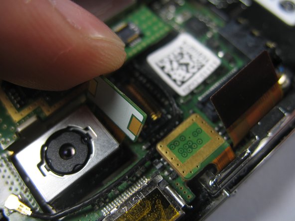
Remove the remaining three ribbon cables by gently lifting them by the ends, opposite of the cables, with a plastic opening tool or spudger until they pop out.
-
-
Dieser Schritt ist noch nicht übersetzt. Hilf mit, ihn zu übersetzen!
-
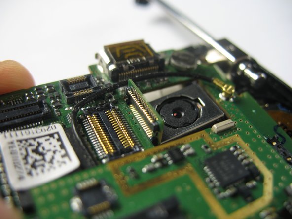
Remove the motherboard by gently prying it up with a spudger from the charging port.
-
Once the board has been lifted, remove it by pulling it away from the connected edge.
-


Rückgängig: Ich habe diese Anleitung nicht absolviert.
Ein:e weitere:r Nutzer:in hat diese Anleitung absolviert.
Team

Cal Poly, Team 8-57, Johann Spring 2013 Mitglied von Cal Poly, Team 8-57, Johann Spring 2013
CPSU-JOHANN-S13S8G57
4 Mitglieder
7 Anleitungen geschrieben