Diese Version enthält möglicherweise inkorrekte Änderungen. Wechsle zur letzten geprüften Version.
Was du brauchst
-
KaufenIn diesem Schritt verwendetes Werkzeug:P5 Pentalobe Screwdriver Retina MacBook Pro and Air$5.99
-
Entferne die folgenden zehn Schrauben:
-
Zwei 8 mm 5-Point Pentalobe Schrauben
-
Acht 2,5 mm 5-Point Pentalobe Schrauben
-
-
-
Löse das Gehäuseunterteil vom Air, indem du mit den Fingerspitzen zwischen Display und Gehäuse gehst und es nach oben ziehst.
-
Entferne das Gehäuseunterteil und lege es beiseite.
-
-
Dieser Schritt ist noch nicht übersetzt. Hilf mit, ihn zu übersetzen!
-
Use the flat end of a spudger to pry both short sides of the battery connector upward to disconnect it from its socket on the logic board.
-
Bend the battery cable slightly away from the logic board so the connector will not accidentally contact its socket.
-
-
Dieser Schritt ist noch nicht übersetzt. Hilf mit, ihn zu übersetzen!
-
Remove the single 2.9 mm T5 Torx screw securing the SSD to the logic board.
So when i change my ssd in mac do i have to reinstall Mac OS
Correct, the SSD does not come with OS preinstalled. To install the OS you can completely clone your existing hard drive or you will need to create a bootable flash drive and format your SSD and create a partition in order to be able to install the OS.
-
-
Dieser Schritt ist noch nicht übersetzt. Hilf mit, ihn zu übersetzen!
-
Use a spudger to help lift the free end of the SSD just enough to grab it with your other hand.
-
Pull the drive straight out of its socket and remove it from the logic board.
I performed all the steps above and fitted a Transcend JetDrive 500 which was very easy however when I re-assembled and turned on all I get is a question mark in the middle of the screen, can you explain if I did anything wrong?
-
-
Dieser Schritt ist noch nicht übersetzt. Hilf mit, ihn zu übersetzen!
-
Use the flat end of a spudger to pry the I/O board cable connector upward out of its socket on the I/O board.
-
-
Dieser Schritt ist noch nicht übersetzt. Hilf mit, ihn zu übersetzen!
-
While gently pulling the I/O board cable upward near its connection to the logic board, use the tip of a spudger to pry upward on alternating sides of the connector to help "walk" it out of its socket.
-
Remove the I/O board cable.
-
-
Dieser Schritt ist noch nicht übersetzt. Hilf mit, ihn zu übersetzen!
-
Use the tip of a spudger to carefully flip up the retaining flap on the fan cable ZIF socket.
-
-
Dieser Schritt ist noch nicht übersetzt. Hilf mit, ihn zu übersetzen!
-
Remove the following three screws securing the fan to the upper case:
-
Two 5.2 mm T5 Torx screws
-
One 3.6 mm T5 Torx screw
-
-
Dieser Schritt ist noch nicht übersetzt. Hilf mit, ihn zu übersetzen!
-
Lift the fan out of the upper case and carefully pull the fan ribbon cable out of its socket as you remove it from the Air.
-
-
-
Dieser Schritt ist noch nicht übersetzt. Hilf mit, ihn zu übersetzen!
-
Remove the following five screws securing the battery to the upper case:
-
Two 5.2 mm T5 Torx screws
-
One 6 mm T5 Torx screw
-
Two 2.6 mm T5 Torx screws
-
-
Dieser Schritt ist noch nicht übersetzt. Hilf mit, ihn zu übersetzen!
-
Lift the battery from its edge nearest the logic board and remove it from the upper case.
-
-
Dieser Schritt ist noch nicht übersetzt. Hilf mit, ihn zu übersetzen!
-
Disconnect the I/O board by pulling the power cable away from its socket on the logic board.
-
-
Dieser Schritt ist noch nicht übersetzt. Hilf mit, ihn zu übersetzen!
-
Use the tip of a spudger or your fingernail to flip up the retaining flap on the trackpad ribbon cable ZIF socket.
-
Pull the trackpad ribbon cable straight out of its socket toward the front edge of the Air.
-
-
Dieser Schritt ist noch nicht übersetzt. Hilf mit, ihn zu übersetzen!
-
Use the tip of a spudger to de-route the right speaker cable from the slot cut into the logic board.
-
-
Dieser Schritt ist noch nicht übersetzt. Hilf mit, ihn zu übersetzen!
-
Use the flat end of a spudger to pry the right speaker cable connector up and out of its socket on the logic board.
-
-
Dieser Schritt ist noch nicht übersetzt. Hilf mit, ihn zu übersetzen!
-
Gently push the tip of a spudger under the black plastic flap stuck to the display data cable lock to make the lock pop upward and away from the socket.
-
While holding the lock away from the socket, use the tip of a spudger and your fingers to gently remove the display data cable from its socket.
-
-
Dieser Schritt ist noch nicht übersetzt. Hilf mit, ihn zu übersetzen!
-
Remove the small rubber gasket from the corner of the upper case near the display data cable.
-
-
Dieser Schritt ist noch nicht übersetzt. Hilf mit, ihn zu übersetzen!
-
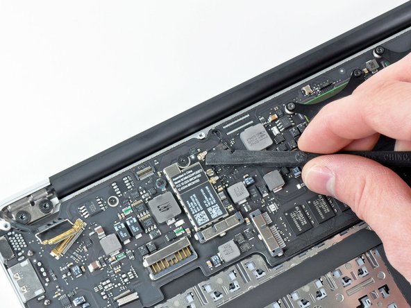
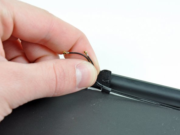
Use the flat end of a spudger to pry both antenna cable connectors up and off their sockets on the AirPort/Bluetooth card.
Heads up when replacing a late 2010 display with a 2011 or later... On later model Airs the wifi card orientation changed, which causes two issues: 1) the antenna cables are longer on the newer displays, so you have excess wire to deal with, 2) On 2010 displays the longer wire goes on the antenna port closer to the battery, on 2011 and later displays the longer cable goes on the port further from the battery (flip-flopped). If you switch them up, your wifi reception will be terrible
-
-
Dieser Schritt ist noch nicht übersetzt. Hilf mit, ihn zu übersetzen!
-
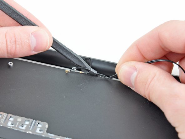
Gently de-route the antenna cables from the slot cut into the logic board.
-
-
Dieser Schritt ist noch nicht übersetzt. Hilf mit, ihn zu übersetzen!
-
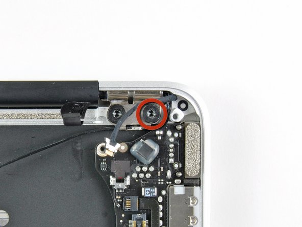
Remove the three 3.6 mm T5 Torx screws securing the logic board to the upper case.
-
-
Dieser Schritt ist noch nicht übersetzt. Hilf mit, ihn zu übersetzen!
-
Gently lift the logic board assembly out of the upper case, minding the fragile heat sink and any cables that may get caught.
-
-
Dieser Schritt ist noch nicht übersetzt. Hilf mit, ihn zu übersetzen!
-
Pull the camera cable parallel to the face of the I/O board toward the rear edge of the Air to disconnect it from its socket.
-
-
Dieser Schritt ist noch nicht übersetzt. Hilf mit, ihn zu übersetzen!
-
Remove the small rubber gasket from the corner of the upper case nearest the I/O board.
-
-
Dieser Schritt ist noch nicht übersetzt. Hilf mit, ihn zu übersetzen!
-
Peel up the six cable loops securing the antenna cables to the upper case.
-
Gently pull the cable loops slightly out of the channel cut into the upper case one at a time.
-
Use your spudger to open up the plastic loops as you de-route the antenna cables through them.
-
Repeat this for all five retaining loops.
The last cable loop on the right side, was actually stuck around the screw which hold the I/O board.
A hole was specially made in the cable loop, it was not an assembling error.
So I had to remove this screw to be able to peel the cable loop.
I actually did the lcd only repair but this guide led me through getting the display out and reassembly. I would recommend this particular guide to anyone! Professional technician or hobbyist.
-
-
Dieser Schritt ist noch nicht übersetzt. Hilf mit, ihn zu übersetzen!
-
Remove the outer 4.9 mm T8 Torx screw securing each display hinge to the upper case (two screws total).
Tried to edit a comment from earlier, but had to delete and start over. I echo Edward's comment but stronger: Try a T-9 before you try a T-8. Or you could end up completely stripping the head before you can even react (one turn, in my case). Then you're left staring at a $500 screw stuck in your MBA case...
-
-
Dieser Schritt ist noch nicht übersetzt. Hilf mit, ihn zu übersetzen!
-
Open the display until it is perpendicular to the upper case and place it on a table as shown.
-
While holding the Air steady, remove the remaining 4.9 mm T8 Torx screw from the lower display bracket.
-
-
Dieser Schritt ist noch nicht übersetzt. Hilf mit, ihn zu übersetzen!
-
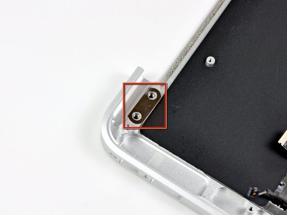
Remove the last 4.9 mm T8 Torx screw securing the display to the upper case.
-
-
Dieser Schritt ist noch nicht übersetzt. Hilf mit, ihn zu übersetzen!
-
Push the upper case slightly toward the display assembly, then rotate it away from the front of the display assembly.
-
Once the two display hinges have cleared the upper case, remove the display and set it aside.
-


Rückgängig: Ich habe diese Anleitung nicht absolviert.
45 weitere Nutzer:innen haben diese Anleitung absolviert.

3 Kommentare
Can I change the flex cable... the display cable in a macbook air? Or I have to change all the display? thank
You can change it, but you have to buy the cable with the hinge and change both because it goes together.
One of the antenna cables got stuck in one of the loops, so I pulled it and the antenna connector got off. Now I can’t connect to the Internet. And there is no easy or cheap fix for this problem. So, people, be careful. Better to cut open some of the loops around antenna cables than make my mistake.
I recommend that one of the tools you obtain is a jeweler's loupe that mounts on your glasses. It makes things easier.
blairweaver - Antwort
This is not correct. You need the pentalobe tool at this point.
Duane Hellums - Antwort