Diese Version enthält möglicherweise inkorrekte Änderungen. Wechsle zur letzten geprüften Version.
Was du brauchst
-
-
Nimm eine Münze oder einen Spudger (Spatel), um die Akku-Verriegelungsschraube um 90 Grad im Uhrzeigersinn zu drehen.
-
-
-
Entferne die drei im gleichen Abstand an der Rückwand des Akkufachs verteilten Kreuzschlitzschrauben.
-
-
-
Fasse die L-förmige Speicherabdeckung am rechten Ende an und ziehe sie zu dir hin, so dass die Öffnung des Akkufachs frei liegt.
-
Hebe sie dann nach oben aus dem Computer heraus.
-
-
-
Entferne die folgenden drei Schrauben:
-
Eine 11 mm Kreuzschlitzschraube #00 in der Mitte des unteren Gehäuses. (Kopf: 5 mm Diameter, Dicke: 0,75 mm)
-
Zwei 14,5 mm Kreuzschlitzschrauben #00 (Kopf: 5 mm Diameter, Dicke: 0,75 mm)
-
-
-
Entferne die folgenden drei Schrauben von der Rückwand des Akku-Gehäuses:
-
Eine 3 mm Kreuzschlitzschraube #0. (Kopf: 2,75 mm Diameter)
-
Zwei 4 mm Kreuzschlitzschrauben #0 auf jeder Seite. (Kopf: 2,75 mm Diameter)
-
-
-
Entferne die beiden Kreuzschlitzschrauben auf beiden Seiten der rechten Wand des Akkufachs (nicht die, die sich direkt neben dem Akkuanschluss befinden).
-
Zwei 6,25 mm Kreuzschlitzschrauben #000. (Kopf: 4 mm Diameter, Dicke: 0,5 mm)
-
-
-
Entferne die vier gekennzeichneten Kreuzschlitzschrauben an der Vorderwand des Akkufachs. Wenn du von links aus arbeitest, entferne die 2., 4., 7. und 9. Schraube.
-
Vier 3,25 mm Kreuzschlitzschrauben #000. (Kopf: 4 mm Diameter, Dicke: 0,4 mm)
-
-
-
Entferne die folgenden vier Schrauben auf der Rückseite des Computers:
-
Zwei 11 mm Kreuzschlitzschrauben #00, mit Schaft (2,2 mm Diameter x 2 mm Länge) (Kopf: 3,2 mm Diameter , Dicke: 0,5 mm)
-
Zwei 7,25 mm Kreuzschlitzschrauben #00, mit Schaft (2 mm Diameter, 3,75 mm Länge) (Kopf: 3,2 mm Diameter, Dicke 0,5mm)
-
-
-
Entferne die beiden Kreuzschlitzschrauben von der rechten Seite des Computers. Das ist die Seite mit dem optischen Laufwerk.
-
Zwei 5,2 mm Kreuzschlitzschrauben #00 mit Schaft (Diameter: 2,3 mm,Länge: 3,25 mm) (Kopf: 3,2 mm Diameter, 0,5 mm Dicke)
-
-
-
Verwende ein Öffnungswerkzeug aus Plastik, eine abgelaufene Kreditkarte oder eine ähnlich dicke Karte, um das obere Gehäuse aufzuhebeln, indem du in der linken oberen Ecke beginnst und dich zur Vorderseite des Computers vorarbeitest.
-
-
-
Halte das obere Gehäuse hoch und ziehe die schwarze Lasche am Steckerende des silbernen Flachbandkabels von seinem Anschluss auf dem Logic Board weg.
-
-
-
Greife die weiße Kunststofflasche an der Festplatte und ziehe sie nach links, um die Festplatte aus dem Computer zu entfernen.
-
-
-
Entferne die beiden Kreuzschlitzschrauben an der Seite des optischen Laufwerks.
-
Zwei 3,25 mm Kreuzschlitzschrauben #000 (Kopf: 4 mm Diameter, 0,3 mm Dicke)
-
-
-
Trenne den orangefarbenen Flachbandkabelstecker des optischen Laufwerks vom Logic Board, indem du ihn entweder mit einem Finger oder einem Spudger gerade nach oben hebelst.
-
-
-
Ziehe den Stecker des neu freigelegten Display-Datenkabels vom Logic Board ab, indem du ihn mit Hilfe seiner schwarzen Zuglasche nach oben ziehst.
-
-
-
Ziehe den Stecker des neu freigelegten Festplattenkabels vom Logic Board ab, indem du ihn an der schwarzen Lasche nach oben ziehst.
-
-
-
Ziehe das Folienband zwischen dem Lüfter und dem optischen Laufwerk ab. Hebe das Folienband von der Seite des Lüfters ab, wobei es am optischen Laufwerk befestigt bleibt.
-
Achte beim Wiederzusammenbau darauf, die Kabel unter dem Klebeband zu verlegen, bevor du es wieder anbringst.
-
-
-
Ziehe das Display-Datenkabel an der Kante des optischen Laufwerks nach oben, um eine silberfarbene Kreuzschlitzschraube freizulegen.
-
-
-
Entferne die 2 mm Kreuzschlitzschraube #00, mit der die hintere Ecke des optischen Laufwerks befestigt ist.
-
Möglicherweise verdeckt das Bluetooth-Kabel mit der silbernen Ummantelung die Schraube. Wenn dies der Fall ist, schiebe es vorsichtig zur Seite. Möglicherweise musst du die Schraube entfernen, die die Erdungslaschen für die beiden benachbarten Kabel hält, bevor du das Bluetooth-Kabel ausreichend zur Seite schieben kannst.
-
-
-
-
Hebe die Bluetooth-Antennenkarte von der Vorderkante des optischen Laufwerks ab.
-
-
-
Führe das Festplattenkabel unter den Clips auf der Seite des optischen Laufwerks heraus.
-
-
-
Hebe die Seite des optischen Laufwerks an, die dir am nächsten ist, und schiebe dann das Laufwerk zu dir hin und nach oben aus dem Computer heraus.
-
Schiebe zunächst die Seite, die der Rückseite des Macbook am nächsten ist, unter die Kante des hinteren Rahmens links vom Scharnier und schiebe gleichzeitig die Befestigungslasche des optischen Laufwerks in der oberen linken Ecke unter die Kabel an dieser Stelle.
-
Senke das Laufwerk teilweise in das untere Gehäuse ab. Halte das Festplattenkabel vom Einschub des optischen Laufwerks fern.
-
Bevor du das Laufwerk vollständig einsetzt, drücke mit einem Spudger nach vorne (zur Vorderseite des Laufwerks hin) auf das Schraubloch in der Befestigungslasche des Laufwerks.
-
Drücke den Schieber, der an der anderen Seite des Laufwerks verläuft, nach vorne, um das Ende dieses Schiebers in einen kleinen Kanal im unteren Gehäuserahmen einzusetzen. Dadurch wird das Laufwerk in seiner Position gehalten.
-
-
Dieser Schritt ist noch nicht übersetzt. Hilf mit, ihn zu übersetzen!
-
For original Macbook Core Duo and Core 2 Duo models, remove these 3 screws:
-
Two 3 mm Phillips near the right speaker.
-
One 6 mm Phillips threaded through a hole in a plastic finger above the subwoofer.
-
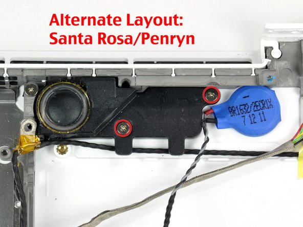
For Santa Rosa/Penryn and 2009 models, which don't have a c-channel:
-
Remove only the single 3 mm Phillips screw from the right speaker, and skip step 26.
-
-
Dieser Schritt ist noch nicht übersetzt. Hilf mit, ihn zu übersetzen!
-
Lift the right speaker out of its housing and set it to the side.
-
-
Dieser Schritt ist noch nicht übersetzt. Hilf mit, ihn zu übersetzen!
-
Using a spudger, gently pry up the white plastic slot and slide the metal c-channel to the right and away from the display.
-
-
Dieser Schritt ist noch nicht übersetzt. Hilf mit, ihn zu übersetzen!
-
Use a spudger to carefully disconnect the microphone cable from the logic board. You'll want to work from side to side, and slowly wiggle the plug back and out of its socket.
-
-
Dieser Schritt ist noch nicht übersetzt. Hilf mit, ihn zu übersetzen!
-
Lift up on the black right speaker cable with one hand, and deroute the microphone cable from the silver metal clip just above the right RAM slot.
-
-
Dieser Schritt ist noch nicht übersetzt. Hilf mit, ihn zu übersetzen!
-
If you didn't remove the ground lug retaining screw in step 20 above, remove it now. It's a 7mm (may be 4mm or 3mm in Santa Rosa/Penryn and 2009 models) Phillips screw securing the ground lugs on the right speaker cable and microphone cable to the metal frame.
-
-
Dieser Schritt ist noch nicht übersetzt. Hilf mit, ihn zu übersetzen!
-
Deroute the microphone cable and the black display data cable from the tabs at the bottom of the subwoofer.
-
-
Dieser Schritt ist noch nicht übersetzt. Hilf mit, ihn zu übersetzen!
-
Remove the single 3 mm Phillips screw securing the ground lug in the display data cable located just above the Bluetooth board. This screw may also be securing a ground lug in the speaker cable.
-
-
Dieser Schritt ist noch nicht übersetzt. Hilf mit, ihn zu übersetzen!
-
Disconnect the antenna cables from the Airport card:
-
If you have an original MacBook Core Duo or Core 2 Duo model, see the first picture, which shows that there are three antenna cables.
-
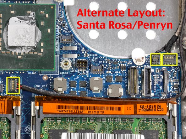
If you have a MacBook Core 2 Duo Santa Rosa/Penryn or 2009 model, there are only two antenna cables, and the plug/socket for the black inverter cable is in a different location. There may be a square foam piece over the plug/socket for the inverter board connector.
-
Disconnect the inverter cable from its socket by inserting a spudger between the right or left ends of the plug and the socket, and prying gently vertically. Do NOT pry up on the socket--you must pull up on the plug alone, vertically out of the socket. Do not pull in the direction of the cable wires or you will tear the socket off the logic board.
-
-
Dieser Schritt ist noch nicht übersetzt. Hilf mit, ihn zu übersetzen!
-
For original Macbook Core Duo and Core 2 Duo models, see first picture and remove the following 2 screws from the right hinge mount:
-
One 6 mm Phillips on the left side of the hinge mount.
-
One 10 mm Phillips on the right side of the hinge mount.
-
For Santa Rosa/Penryn and 2009 models, see second picture and remove the following 3 screws from the right hinge mount:
-
One 3 mm smalller diameter Phillips on the far left.
-
One 5.2 mm larger diameter, 4.2 mm head Phillips in the middle.
-
One 10 mm larger diameter, 4.2mm head Phillips from the far right.
-
Before removing the right hinge mount, take care to see how its pieces fit together, including the small white plastic piece. Knowing how the mount pieces fit together will help with reassembly. Lift the right hinge mount with the small white plastic piece out of the computer.
-
-
Dieser Schritt ist noch nicht übersetzt. Hilf mit, ihn zu übersetzen!
-
Hold the display with one hand while removing the following 3 screws from the left hinge mount:
-
One 7.2 mm smaller diameter Phillips from the right side.
-
One 5.2 mm larger diameter Phillips from the middle.
-
One larger diameter 10 mm Phillips from the left side.
-
Lift the left hinge mount with white plastic piece out of the computer.
-
Check that the cables coming out of the right end of the left hinge are not trapped under other cables.
-
-
Dieser Schritt ist noch nicht übersetzt. Hilf mit, ihn zu übersetzen!
-
Grasp the display assembly on either side and lift it up and out of the computer, taking care that the cables attached to the display don't snag on parts in the lower case.
-
-
Dieser Schritt ist noch nicht übersetzt. Hilf mit, ihn zu übersetzen!
-
Peel up the small black rubber cover from the right side of the heat sink.
-
-
Dieser Schritt ist noch nicht übersetzt. Hilf mit, ihn zu übersetzen!
-
Core Duo and original Core 2 Duo models (photo 1):Disconnect the two newly-revealed temperature sensor connectors and the fan connector from the logic board. These connectors move up vertically off of the logic board, NOT pulled towards the rear of the case, and can be lifted with gentle pressure from under the cable.
-
Santa Rosa/Penryn models (photo 2): There is only one temperature sensor connector containing all four wire leads.
-
Early and Mid 2009 models don't have a separate temperature sensor attached to the heat sink, and thus no cable for it, so nothing is plugged into the temperature sensor connector.
-
-
Dieser Schritt ist noch nicht übersetzt. Hilf mit, ihn zu übersetzen!
-
Remove the following 6 screws:
-
One 3 mm Phillips on the right side of the fan.
-
One 6 mm or 7mm Phillips on the left side of the fan.
-
Four 8mm or 9 mm Phillips securing the heat sink to the lower case.
-
-
Dieser Schritt ist noch nicht übersetzt. Hilf mit, ihn zu übersetzen!
-
Hold the heat sink with one hand and the fan with your other hand, and lift the heat sink and fan assembly out of the computer. The fan is attached to the heat sink only with a strip of black felt tape, so be sure to remove both parts as a unit.
-
-
Dieser Schritt ist noch nicht übersetzt. Hilf mit, ihn zu übersetzen!
-
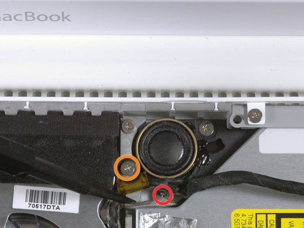
Remove the following two screws:
-
One 3mm screw securing the MagSafe board to the lower case.
-
One 7.5mm screw securing the left speaker to the lower case.
-
-
Dieser Schritt ist noch nicht übersetzt. Hilf mit, ihn zu übersetzen!
-
De-route the left speaker cable from the two clips on the left I/O frame.
-
-
Dieser Schritt ist noch nicht übersetzt. Hilf mit, ihn zu übersetzen!
-
Use a spudger to lift the left speaker out of its housing. Grasp it with your fingers and set it aside.
-
-
Dieser Schritt ist noch nicht übersetzt. Hilf mit, ihn zu übersetzen!
-
Disconnect the MagSafe board connector plug from the logic board, by grasping its cable and pulling it to the right.
-
-
Dieser Schritt ist noch nicht übersetzt. Hilf mit, ihn zu übersetzen!
-
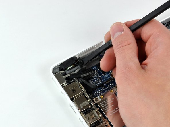
Use your left hand to move the MagSafe board cable enough to uncover the screw at the top end of the left I/O frame.
-
Remove the 7.5 mm Phillips screw from the top end of the left I/O frame.
-
-
Dieser Schritt ist noch nicht übersetzt. Hilf mit, ihn zu übersetzen!
-
Remove the following 2 screws:
-
One 7.5 mm Phillips from the bottom end of the left I/O frame.
-
One 8 or 9 mm Phillips from the middle of the left I/O frame.
-
-
Dieser Schritt ist noch nicht übersetzt. Hilf mit, ihn zu übersetzen!
-
Lift the left I/O frame up and out of the computer. Pay attention to the thin metal EMI fingers, as they may catch as you remove the left I/O frame, especially the two fingers, above the Firewire and headphone ports, which have hooks that engage with holes in the second EMI metal shield, which runs along the front of the I/O ports.
-
-
Dieser Schritt ist noch nicht übersetzt. Hilf mit, ihn zu übersetzen!
-
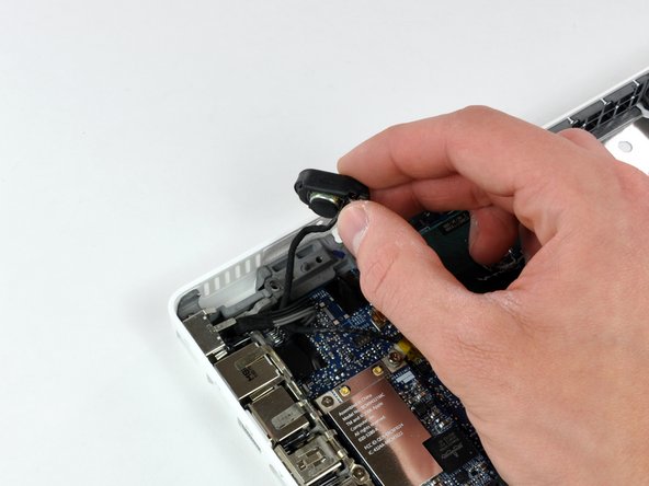
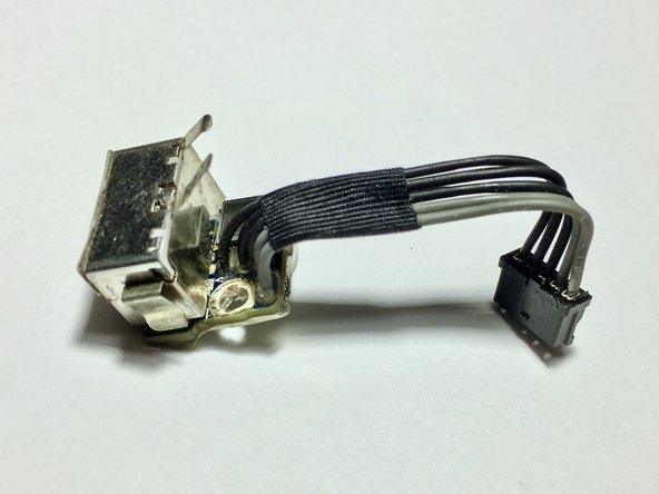
The MagSafe board is now free of all connections and can be detached freely from the logic board.
-
Using your fingers, pull out the MagSafe board.
-
-
Dieser Schritt ist noch nicht übersetzt. Hilf mit, ihn zu übersetzen!
-
Remove the two 4 mm Phillips shoulder screws attaching the battery connector to the lower case.
-
-
Dieser Schritt ist noch nicht übersetzt. Hilf mit, ihn zu übersetzen!
-
Remove the single 6.5mm Phillips screw in the upper right corner of the Airport card. This screw will have a thicker/taller cylindrical head.
-
-
Dieser Schritt ist noch nicht übersetzt. Hilf mit, ihn zu übersetzen!
-
Use a spudger to disconnect the right speaker connector and the Bluetooth connector from the logic board. Both of these connector plugs are removed by prying them gently upward, NOT by pulling them horizontally.
-
-
Dieser Schritt ist noch nicht übersetzt. Hilf mit, ihn zu übersetzen!
-
Remove the three 3 mm Phillips screws securing the logic board to the lower case.
-
-
Dieser Schritt ist noch nicht übersetzt. Hilf mit, ihn zu übersetzen!
-
Lift the logic board up from its right side, slide it to the right slightly, and then up and out of the lower case. If the I/O ports don't easily release from the left side of the housing, gently pull up the lower left corner of the logic board by pulling up on the battery connector cable.
-
-
Dieser Schritt ist noch nicht übersetzt. Hilf mit, ihn zu übersetzen!
-
Remove the two 3.5mm Phillips screws securing the subwoofer to the lower case.
-
-
Dieser Schritt ist noch nicht übersetzt. Hilf mit, ihn zu übersetzen!
-
Deroute the right speaker and Bluetooth antenna cables from their slots in the lower case.
-
-
Dieser Schritt ist noch nicht übersetzt. Hilf mit, ihn zu übersetzen!
-
Pry the Bluetooth board up from the lower case.
-
Lift the subwoofer, right speaker, Bluetooth board, and attached cables out of the computer.
-
-
Dieser Schritt ist noch nicht übersetzt. Hilf mit, ihn zu übersetzen!
-
On Santa Rosa/Penryn models, use a spudger to pry up the PRAM battery and remove it from the lower case.
-
-
Dieser Schritt ist noch nicht übersetzt. Hilf mit, ihn zu übersetzen!
-
Remove the two 6 mm Phillips shoulder screws securing the hard drive connector to the lower case.
-
-
Dieser Schritt ist noch nicht übersetzt. Hilf mit, ihn zu übersetzen!
-
Carefully lift the hard drive connector out of the case slightly, and turn it over to reveal the IR sensor's ribbon cable connector beneath. Use a spudger to flip up the tiny locking bar holding the end of the cable in place.
-
Slide the orange IR sensor cable out of its connector, and lift the hard drive connector out of the computer. The IR sensor, its ribbon cable, and its small circuit board remain in place on the lower case.
-


Rückgängig: Ich habe diese Anleitung nicht absolviert.
49 weitere Nutzer:innen haben diese Anleitung absolviert.
