Diese Version enthält möglicherweise inkorrekte Änderungen. Wechsle zur letzten geprüften Version.
Was du brauchst
-
-
Ziehe die beiden Laschen, die den Akku im Laptop halten, mit den Fingern vom Akku weg und nimm den Akku aus dem Rechner heraus.
-
-
-
Entferne die drei Kreuzschlitz Schrauben von der Abdeckung des Arbeitsspeichers.
-
-
-
Hebe die Abdeckung hoch genug, um sie greifen zu können und ziehe sie vom Rechner weg.
-
-
-
Entferne die beiden 2,8 mm Kreuzschlitz Schrauben im Bereich des Akkufachs.
-
-
-
Entferne die folgenden sechs Schrauben:
-
Jeweils eine 10 mm T6 Torx Schraube rechts und links vom Arbeitsspeicher.
-
Vier 14,5 mm Kreuzschlitz Schrauben entlang des Bildschirm-Scharniers.
-
-
-
Entferne die vier 3,2 mm Kreuzschlitz Schrauben entlang der Seite mit den Anschlüssen des Computers.
-
-
-
Drehe den Computer um 90° und entferne die beiden 3,2 mm Kreuzschlitz Schrauben von der Rückseite des Computers.
-
-
-
Drehe den Computer noch einmal um 90° und entferne die vier 3,2 mm Kreuzschlitz Schrauben von der Seite des Computers.
-
-
-
Hebe die Rückseite des oberen Gehäuses an und arbeite dich mit deinen Fingern an beiden Seiten des Computers nach unten und löse die Klammern, die das obere Gehäuse mit dem Rest des Computers verbinden.
-
Wenn das obere Gehäuse sich noch nicht löst, bewege es auf und ab, um noch weitere Klammern zu lösen. Es gibt einige versteckte Klammern, die sich lösen müssen.
-
-
-
Trenne das Trackpad- und Tastatur-Flachbandkabel von der Hauptplatine. Möglicherweise ist der Anschluss mit einem Klebestreifen abgedeckt.
-
Entferne das obere Gehäuse.
-
-
Dieser Schritt ist noch nicht übersetzt. Hilf mit, ihn zu übersetzen!
-
Disconnect the orange SuperDrive ribbon cable from the logic board, removing tape as necessary.
-
-
Dieser Schritt ist noch nicht übersetzt. Hilf mit, ihn zu übersetzen!
-
Remove the following 4 screws:
-
Two 3.3 mm silver Phillips screws on either side of the SuperDrive.
-
One 4.7 mm silver T6 Torx screw from the top left corner of the drive
-
One 6.2 mm black Phillips screw at the top right corner of the drive.
-
-
Dieser Schritt ist noch nicht übersetzt. Hilf mit, ihn zu übersetzen!
-
Lift the optical drive up and out of the computer.
-
-
Dieser Schritt ist noch nicht übersetzt. Hilf mit, ihn zu übersetzen!
-
Disconnect the hard drive and ExpressCard connectors from the left side of the logic board.
-
-
Dieser Schritt ist noch nicht übersetzt. Hilf mit, ihn zu übersetzen!
-
Disconnect the iSight and display data cables from the logic board by sliding the cables out of their connectors, removing tape as necessary.
-
-
Dieser Schritt ist noch nicht übersetzt. Hilf mit, ihn zu übersetzen!
-
Disconnect the eight indicated connectors by placing a spudger beneath each cable and lifting up.
-
-
-
Dieser Schritt ist noch nicht übersetzt. Hilf mit, ihn zu übersetzen!
-
Remove the silver T6 Torx screw securing the ground loop in the display data cable to the casing.
-
-
Dieser Schritt ist noch nicht übersetzt. Hilf mit, ihn zu übersetzen!
-
Remove the single T6 Torx screw securing the clear plastic shield over the right ambient light sensor.
-
Lift the clear plastic shield off the right ambient light sensor.
-
-
Dieser Schritt ist noch nicht übersetzt. Hilf mit, ihn zu übersetzen!
-
Peel up the orange Kapton tape securing the right thermal sensor cable to the logic board.
-
-
Dieser Schritt ist noch nicht übersetzt. Hilf mit, ihn zu übersetzen!
-
Remove the following 15 screws:
-
One 4.4 mm black Phillips screw to the right of the ram slot.
-
Eight 4.7 mm silver T6 Torx screws securing the logic board to the lower case.
-
One 6.2 mm black T6 Torx screw on the right side of the left fan.
-
Five 9.4 mm silver T6 Torx screws securing the left and right fans.
-
-
Dieser Schritt ist noch nicht übersetzt. Hilf mit, ihn zu übersetzen!
-
Hold the logic board down with one hand and use your other hand to lift the left fan up from its housing. There is a piece of black tape securing the fan to the heat sink. Carefully peel this tape up from the heat sink as you lift the fan up.
-
Place the fan above the Airport card. It is not necessary to remove the fan from the computer entirely.
-
-
Dieser Schritt ist noch nicht übersetzt. Hilf mit, ihn zu übersetzen!
-
Lift the right fan up and carefully peel up the tape securing the fan to the heat sink as you go.
-
Remove the right fan from the computer.
-
-
Dieser Schritt ist noch nicht übersetzt. Hilf mit, ihn zu übersetzen!
-
Lift up the left side of the logic board and disconnect the gray and black power cable from the bottom of the board.
-
-
Dieser Schritt ist noch nicht übersetzt. Hilf mit, ihn zu übersetzen!
-
Grasp the logic board at the left side and at the thin section, and rotate the logic board out of the lower case.
-
-
Dieser Schritt ist noch nicht übersetzt. Hilf mit, ihn zu übersetzen!
-
Lift the heat sink out of the computer.
-
-
Dieser Schritt ist noch nicht übersetzt. Hilf mit, ihn zu übersetzen!
-
Peel up the left ambient light sensor cable from above the left fan, removing tape as necessary.
-
Remove the left fan from the computer.
-
-
Dieser Schritt ist noch nicht übersetzt. Hilf mit, ihn zu übersetzen!
-
Disconnect the three antenna cables attached to the Airport Extreme card.
-
-
Dieser Schritt ist noch nicht übersetzt. Hilf mit, ihn zu übersetzen!
-
Deroute the Airport antenna cables from their channel in the left speaker.
-
-
Dieser Schritt ist noch nicht übersetzt. Hilf mit, ihn zu übersetzen!
-
Remove the single black T6 Torx screw located just above the Airport Extreme card.
-
Lift the small silver metal retaining bracket up and out of the computer.
-
-
Dieser Schritt ist noch nicht übersetzt. Hilf mit, ihn zu übersetzen!
-
Lift the Airport Extreme card up and slide it out of its connector.
-
-
Dieser Schritt ist noch nicht übersetzt. Hilf mit, ihn zu übersetzen!
-
Peel up the orange hard drive cable from above the ExpressCard cage.
-
-
Dieser Schritt ist noch nicht übersetzt. Hilf mit, ihn zu übersetzen!
-
Disconnect the speaker cable from the corner of the left I/O board.
-
-
Dieser Schritt ist noch nicht übersetzt. Hilf mit, ihn zu übersetzen!
-
Carefully peel up the black adhesive tape securing the speaker cable along the rear edge of the lower case.
-
-
Dieser Schritt ist noch nicht übersetzt. Hilf mit, ihn zu übersetzen!
-
Continue to free the speaker cable from the black tape until it is free from all three sections of tape.
-
-
Dieser Schritt ist noch nicht übersetzt. Hilf mit, ihn zu übersetzen!
-
Remove the single black T6 Torx screw securing the right speaker to the lower case.
-
-
Dieser Schritt ist noch nicht übersetzt. Hilf mit, ihn zu übersetzen!
-
Use a spudger to pry up the right speaker from the lower case.
-
Remove the speakers from the computer.
-
-
Dieser Schritt ist noch nicht übersetzt. Hilf mit, ihn zu übersetzen!
-
Support the display with one hand while removing the following 3 screws:
-
Two 9.5 mm silver T6 Torx screws with threads on only part of the shaft on the inside of the display hinges.
-
One 9.5 mm silver T6 Torx screw with threads on the entire shaft on the outside of the left hinge.
-
-
Dieser Schritt ist noch nicht übersetzt. Hilf mit, ihn zu übersetzen!
-
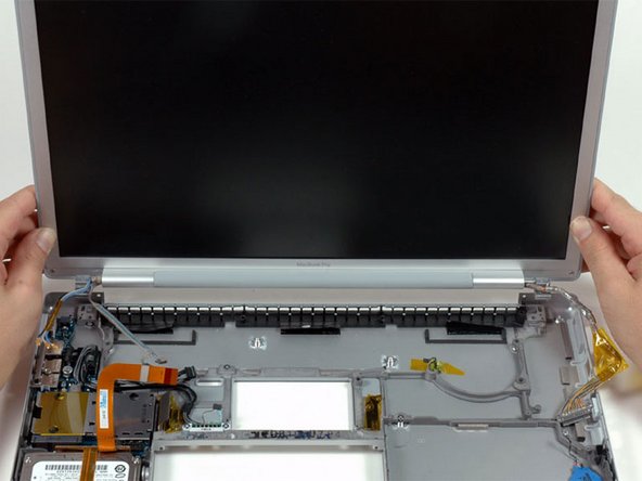
Grasp the display assembly on both sides and lift it up and out of the computer.
-
-
Dieser Schritt ist noch nicht übersetzt. Hilf mit, ihn zu übersetzen!
-
Disconnect the IR and sleep light cables from their connectors above the hard drive.
-
-
Dieser Schritt ist noch nicht übersetzt. Hilf mit, ihn zu übersetzen!
-
Remove the two silver Phillips screws securing the hard drive retaining bracket to the lower case.
-
Lift the hard drive retaining bracket up and out of the computer.
-
-
Dieser Schritt ist noch nicht übersetzt. Hilf mit, ihn zu übersetzen!
-
Lift the hard drive up from the right side and remove it and the attached cable from the computer.
-
-
Dieser Schritt ist noch nicht übersetzt. Hilf mit, ihn zu übersetzen!
-
Remove the following 7 screws/standoffs:
-
Four black T6 Torx screws securing the left I/O board to the lower case.
-
Two silver T6 Torx screws securing the battery connector to the lower case.
-
One 4 mm standoff located between the audio jacks.
-
-
Dieser Schritt ist noch nicht übersetzt. Hilf mit, ihn zu übersetzen!
-
Lift the left I/O board up from the right side and slide it out of the computer.
-
-
Dieser Schritt ist noch nicht übersetzt. Hilf mit, ihn zu übersetzen!
-
Peel up the orange Kapton tape covering the right thermal sensor.
-
Use a spudger to pry the right thermal sensor off the lower case.
-
-
Dieser Schritt ist noch nicht übersetzt. Hilf mit, ihn zu übersetzen!
-
Use a spudger to pry up the PRAM battery off the lower case.
-


Rückgängig: Ich habe diese Anleitung nicht absolviert.
19 weitere Nutzer:innen haben diese Anleitung absolviert.
