Diese Version enthält möglicherweise inkorrekte Änderungen. Wechsle zur letzten geprüften Version.
Was du brauchst
-
-
Benutze deine Finger und drücke bzw. ziehe die beiden Entriegelungslaschen vom Akku weg, und hebe den Akku aus dem Computer.
-
-
-
Entferne die drei identischen 2 mm Kreuzschlitzschrauben von der RAM Abdeckung.
-
Hebe die Abdeckung soweit hoch, dass du sie fassen kannst und ziehe sie weg vom Gehäuse zu dir hin.
-
-
-
Entferne die beiden 2,8 mm Kreuzschlitzschrauben im Akkufach in der Nähe der Verriegelung.
-
-
-
Entferne folgende sechs Schrauben:
-
Zwei 10 mm Torx T6 Schrauben auf jeder Seite des RAM- Einschubs.
-
Vier 14,5 mm Kreuzschlitzschrauben am Scharnier.
-
-
-
Entferne die vier 3,2 mm #00 Kreuzschlitzschrauben an der Seite mit den Anschlüssen.
-
-
-
Drehe den Computer um 90° und entferne die beiden 3,2 mm Kreuzschlitzschrauben auf der Rückseite des Computers.
-
-
-
Drehe den Computer weitere 90° und entferne die vier 3,2 mm Kreuzschlitzschrauben an der Seite des Computers.
-
-
-
Hebe das Gehäuse hinten hoch und arbeite dich dann mit den Fingern an den Seiten entlang nach vorne. Wenn die Seiten frei sind, dann bewege es auf und ab, sodass sich auch die Vorderkante ablöst.
-
Es gibt vier Kunststoffrasten über den DVD-Einschub und eine weitere links über dem Infrarotsensor. Diese Rasten lassen sich kaum lösen, ohne zu hebeln. Beim Zusammenbau sind sie auch wieder schwer einzurasten.
-
-
-
-
Trenne die Flachbandkabel des Trackpads und der Tastatur vom Logic Board ab, wobei du eventuell Klebebänder ablösen musst.
-
Entferne das Gehäuseoberteil.
-
-
-
Benutze das flache Ende eines Spudgers, um das orangefarbene SuperDrive Flachbandkabel vom Logic Board abzutrennen. Eventuell musst du etwas Klebeband entfernen.
-
-
-
Entferne die folgenden vier Schrauben:
-
Zwei silberfarbene 3,3 mm Kreuzschlitzschrauben auf jeder Seite des SuperDrive.
-
Eine silberfarbene 4,7 mm Kreuzschlitzschrauben an der oberen linken Ecke des Laufwerks.
-
Eine schwarze 6,2 mm Kreuzschlitzschrauben an der oberen rechten Ecke des Laufwerks.
-
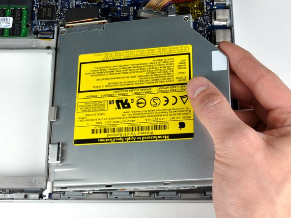
Hebe das optische Laufwerk an und entferne es aus dem Computer.
-
-
Dieser Schritt ist noch nicht übersetzt. Hilf mit, ihn zu übersetzen!
-
Disconnect the hard drive and ExpressCard connectors from the left side of the logic board.
-
-
Dieser Schritt ist noch nicht übersetzt. Hilf mit, ihn zu übersetzen!
-
Disconnect the iSight and display data cables from the logic board by sliding them straight back out of their connectors, removing tape as necessary.
-
-
Dieser Schritt ist noch nicht übersetzt. Hilf mit, ihn zu übersetzen!
-
Disconnect the eight indicated connectors by placing a spudger beneath the wired side of each one and lifting up.
-
-
Dieser Schritt ist noch nicht übersetzt. Hilf mit, ihn zu übersetzen!
-
Remove the foam bumper from the top of the right hinge of the display.
-
-
Dieser Schritt ist noch nicht übersetzt. Hilf mit, ihn zu übersetzen!
-
Remove the silver 9.5 mm T6 Torx screw securing the ground loop in the display data cable to the casing.
-
-
Dieser Schritt ist noch nicht übersetzt. Hilf mit, ihn zu übersetzen!
-
Remove the single black 6 mm T6 Torx screw securing the upper portion of the logic board to the lower case.
-
-
Dieser Schritt ist noch nicht übersetzt. Hilf mit, ihn zu übersetzen!
-
Peel up the orange Kapton tape securing the right thermal sensor cable to the logic board.
-
-
Dieser Schritt ist noch nicht übersetzt. Hilf mit, ihn zu übersetzen!
-
Remove the following 15 screws:
-
One 4.4 mm black Phillips screw to the right of the ram slot.
-
Eight 4.7 mm silver T6 Torx screws securing the logic board to the lower case.
-
One 6.2 mm black T6 Torx screw on the right side of the left fan.
-
Five 9.4 mm silver T6 Torx screws securing the left and right fans.
-
-
Dieser Schritt ist noch nicht übersetzt. Hilf mit, ihn zu übersetzen!
-
Hold the logic board down with one hand and use your other hand to lift the left fan up from its housing. There is a piece of black tape securing the left fan to the heat sink. Carefully peel this tape up from the heat sink as you lift the left fan up.
-
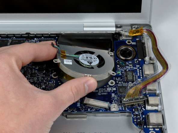
Lift the right fan up and carefully peel up the tape securing the fan to the heat sink as you go.
-
Remove the right fan from the computer.
-
-
Dieser Schritt ist noch nicht übersetzt. Hilf mit, ihn zu übersetzen!
-
Lift up the left side of the logic board and disconnect the gray and black power cable from the bottom of the board.
-
Grasp the logic board at the left side and at the thin section, and rotate the logic board out of the lower case.
-
-
Dieser Schritt ist noch nicht übersetzt. Hilf mit, ihn zu übersetzen!
-
Gently lift the heat sink out of the computer.
-
Peel back the orange Kapton tape covering the middle thermal sensor.
-
Use a spudger to pry the middle thermal sensor off the heat sink.
-
Heat sink remains.
-
-
Dieser Schritt ist noch nicht übersetzt. Hilf mit, ihn zu übersetzen!
-
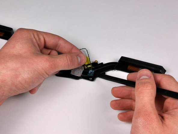
Peel back the piece of tape covering the left thermal sensor.
-
-
Dieser Schritt ist noch nicht übersetzt. Hilf mit, ihn zu übersetzen!
-
Use the flat end of a spudger to pry the left thermal sensor board off the adhesive securing it to the lower case.
-


Rückgängig: Ich habe diese Anleitung nicht absolviert.
5 weitere Nutzer:innen haben diese Anleitung absolviert.
