Diese Version enthält möglicherweise inkorrekte Änderungen. Wechsle zur letzten geprüften Version.
Was du brauchst
-
-
Klappe das Display zu und platziere deinen Laptop umgedreht auf einer flachen Oberfläche.
-
Drücke die gerillte Seite der Entriegelunsvorrichtung nach unten und greife den herrausragenden Teil, um ihn nach oben ziehen zu können, bis er vertikal nach oben zeigt.
-
-
-
Fasse die durchsichtige Kunstofflasche an, ziehe den Akku hoch und aus dem Unibody heraus.
-
Wenn die Lasche eingedrückt ist, dann verriegelt sie den Akku.
-
-
-
Entferne die folgenden acht Kreuzschlitzschrauben, mit denen das untere Gehäuseunterteil befestigt ist:
-
Eine 5,4 mm Kreuzschlitzschraube
-
Drei 14 mm Kreuzschlitzschrauben
-
Vier 3,5 mm Kreuzschlitzschrauben
-
-
-
Hebe mit beiden Händen das Gehäuseunterteil vom oberen Gehäuse an und entferne es.
-
-
-
Trenne das Kamerakabel ab, indem du das männliche Ende gerade aus dem Anschluss ziehst.
-
-
-
Verwende einen Spudger, um den Anschluss des optischen Laufwerks gerade nach oben vom Logic Board zu hebeln.
-
-
-
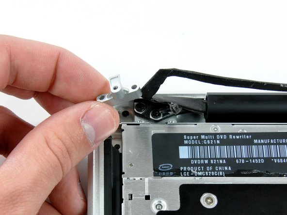
Entferne die beiden 8 mm Kreuzschlitzschrauben, mit denen die Kamerakabelhalterung am oberen Gehäuse befestigt ist.
-
Hebe die Kamerakabelhalterung aus dem oberen Gehäuse heraus.
-
-
-
-
Entferne die folgenden drei Kreuzschlitzschrauben, mit denen das optische Laufwerk am oberen Gehäuse befestigt ist:
-
Eine 3,5 mm Kreuzschlitzschraube.
-
Zwei 2,5 mm Kreuzschlitzschrauben.
-
-
-
Hebe das optische Laufwerk an der linken Kante an und ziehe es aus dem Computer heraus.
-
-
Dieser Schritt ist noch nicht übersetzt. Hilf mit, ihn zu übersetzen!
-
Using the flat end of a spudger, pry the subwoofer connector straight up off the logic board.
-
-
Dieser Schritt ist noch nicht übersetzt. Hilf mit, ihn zu übersetzen!
-
Remove the following four screws securing the subwoofer and right speaker to the upper case:
-
Two 3.2 mm Phillips screws.
-
One 2.6 mm Phillips screw.
-
One 5 mm Phillips screw.
-
-
Dieser Schritt ist noch nicht übersetzt. Hilf mit, ihn zu übersetzen!
-
Lift the subwoofer and right speaker assembly out of the upper case.
-
-
Dieser Schritt ist noch nicht übersetzt. Hilf mit, ihn zu übersetzen!
-
Remove the single Phillips screw securing the hard drive bracket to the upper case.
-
-
Dieser Schritt ist noch nicht übersetzt. Hilf mit, ihn zu übersetzen!
-
Lift the hard drive by its plastic pull tab and remove the freed hard drive bracket.
-
-
Dieser Schritt ist noch nicht übersetzt. Hilf mit, ihn zu übersetzen!
-
Lift the hard drive out of its supports and disconnect the SATA cable by pulling the connector straight away from the hard drive.
-
-
Dieser Schritt ist noch nicht übersetzt. Hilf mit, ihn zu übersetzen!
-
Remove the following 5 screws securing the mid wall to the upper case:
-
Three 10.5 mm Phillips screws.
-
Two 3.7 mm Phillips screws.
-
Lift the mid wall out of the upper case.
-
-
Dieser Schritt ist noch nicht übersetzt. Hilf mit, ihn zu übersetzen!
-
Lift the mid wall out of the upper case.
-
-
Dieser Schritt ist noch nicht übersetzt. Hilf mit, ihn zu übersetzen!
-
Use a spudger to pry the hard drive cable connector straight up off the logic board.
-
-
Dieser Schritt ist noch nicht übersetzt. Hilf mit, ihn zu übersetzen!
-
Peel the hard drive cable from the adhesive securing it to the upper case, and maneuver the plastic retaining block out of the upper case.
-
-
Dieser Schritt ist noch nicht übersetzt. Hilf mit, ihn zu übersetzen!
-
Use the pointed end of a spudger to flip the lock on the ZIF connector.
-
-
Dieser Schritt ist noch nicht übersetzt. Hilf mit, ihn zu übersetzen!
-
Pull the hard drive bracket cable out of its socket.
-
-
Dieser Schritt ist noch nicht übersetzt. Hilf mit, ihn zu übersetzen!
-
Peel the connector side of the sleep sensor cable up from the adhesive securing it to the upper case.
-
-
Dieser Schritt ist noch nicht übersetzt. Hilf mit, ihn zu übersetzen!
-
Remove the two 5 mm Phillips #00 screws securing the hard drive bracket to the upper case.
-
-
Dieser Schritt ist noch nicht übersetzt. Hilf mit, ihn zu übersetzen!
-
Insert the tip of the spudger between the hard drive bracket and the front edge of the upper case to free it from its recess.
-
-
Dieser Schritt ist noch nicht übersetzt. Hilf mit, ihn zu übersetzen!
-
After ensuring that the cable is freed of all adhesive, remove the hard drive bracket and sleep sensor assembly from the upper case.
-


Rückgängig: Ich habe diese Anleitung nicht absolviert.
Ein:e weitere:r Nutzer:in hat diese Anleitung absolviert.

