Diese Version enthält möglicherweise inkorrekte Änderungen. Wechsle zur letzten geprüften Version.
Was du brauchst
-
-
Heble das AirPort/Bluetooth-Flachbandkabel vorsichtig mit dem flachen Ende des Spudgers aus seinem Anschluss auf dem Logic Board.
-
-
-
Ziehe den Stecker des Kamerakabels gerade aus seinem Anschluss auf dem Logic Board heraus.
-
-
-
Löse die drei Antennenstecker mit der Spudgerspitze von der AirPort/Bluetooth Karte.
-
-
-
Löse alle drei Antennenkabel aus ihren Kanälen in der AirPort/Bluetooth Halterung.
-
Fädle das Kamerakabel aus seinem Kanal in der AirPort/Bluetooth Halterung.
-
-
-
Entferne die folgenden beiden Kreuzschlitzschrauben, mit der die AirPort/Bluetooth Einheit am oberen Gehäuse befestigt ist:
-
Eine 3,8 mm Schraube
-
Eine 8,6 mm Schraube
-
-
-
Entferne die AirPort/Bluetooth Einheit vom oberen Gehäuse. Achte dabei darauf, dass sich keine Kabel verfangen.
-
-
-
Entferne die 8,6 mm Kreuzschlitzschraube, mit der der Halter des Antennen-/Kamerakabels am oberen Gehäuse befestigt ist.
-
Entferne den Halter des Antennen-/Kamerakabels vom oberen Gehäuse.
-
-
-
Entferne zwei der drei 6 mm Torx T6 Schrauben, mit der die rechte Seite des Displays am oberen Gehäuse befestigt ist.
-
-
-
Fasse die Plastikzuglasche an der Verriegelung des Displaydatenkabels und kippe sie nach oben über den Stecker in Richtung der Seite am Computer mit der Gleichstromversorgung (DC-in).
-
Ziehe das Displaydatenkabel gerade aus seinem Anschluss auf dem Logic Board heraus.
-
-
-
Entferne die 8,6 mm Kreuzschlitzschraube, mit der der Halter des Displaydatenkabels am oberen Gehäuse befestigt ist.
-
Entferne den Halter des Displaydatenkabels vom oberen Gehäuse.
-
-
-
Entferne zwei der drei 6 mm Torx T6 Schrauben, mit denen die linke Seite des Displays am oberen Gehäuse befestigt ist.
-
-
-
Öffne das MacBook Pro so, dass das Display rechtwinklig zum oberen Gehäuse steht.
-
Stelle das geöffnete Gerät wie gezeigt auf den Tisch.
-
Halte Display und oberes Gehäuse mit der linken Hand zusammen. Drehe dann die verbliebene T6 Torx Schraube aus der oberen Displayhalterung.
-
-
-
-
Drehe die letzte verbliebene T6 Torx Schraube, die das Display noch am oberen Gehäuse befestigt, heraus.
-
-
-
Fasse das obere Gehäuseteil mit der rechten Hand und drehe es leicht in Richtung Oberkante des Displays. Dadurch löst sich die obere Displayhalterung von der Kante des oberen Gehäuses.
-
Drehe das Display leicht vom oberen Gehäuse weg.
-
Hebe das Display hoch und weg vom oberen Gehäuseteil, achte dabei darauf, dass sich keine Halterungen oder Kabel verfangen.
-
-
Dieser Schritt ist noch nicht übersetzt. Hilf mit, ihn zu übersetzen!
-
At the bottom right corner of the screen, insert the pointed side of spudger between the bezel and wide, flat part of rubber bumper. Pull the bumper towards to hinge to release the adhesive.
-
Then place the flat side of the spudger between bezel and bumper at the same location, slip the spudger underneath the bumper and lift.
-
-
Dieser Schritt ist noch nicht übersetzt. Hilf mit, ihn zu übersetzen!
-
Moving up the right side of the screen, begin pulling the bumper out slowly, in approximately 1"-2" increments. Continue around the screen until the bumper is complete removed.
-
-
Dieser Schritt ist noch nicht übersetzt. Hilf mit, ihn zu übersetzen!
-
While applying heat with a heat gun:
-
Place the flat edge of the spudger under the bottom lip of the bezel on the lower right portion of the display assembly.
-
Gently pry the corner of the bezel upward, creating enough space to insert the flat edge of the spudger between the bezel and display assembly.
-
With the flat edge of the spudger under the bezel, gently twist the spudger to release the double stick adhesive tape.
-
-
Dieser Schritt ist noch nicht übersetzt. Hilf mit, ihn zu übersetzen!
-
Continue working up the right side in 1"-1.5" increments:
-
Apply heat to the unreleased area.
-
From the outer edge of the bezel, insert the flat side of the spudger to where it snugly fits under the lifted portion of the bezel.
-
Gently twist the spudger.
-
-
Dieser Schritt ist noch nicht übersetzt. Hilf mit, ihn zu übersetzen!
-
Continue the technique described in the previous step to release the bezel along the top and on the left side.
-
-
Dieser Schritt ist noch nicht übersetzt. Hilf mit, ihn zu übersetzen!
-
To release the lower left of the bezel, while applying heat, insert the flat end of the spudger from the left side, and gently twist to pry up the double stick tape.
-
Repeat above from the right side to release the lower right.
-
-
Dieser Schritt ist noch nicht übersetzt. Hilf mit, ihn zu übersetzen!
-
Remove the bezel from the display assembly.
-
Clean the bottom side of the bezel with isopropyl alcohol and set it aside.
-
-
Dieser Schritt ist noch nicht übersetzt. Hilf mit, ihn zu übersetzen!
-
Remove the LCD following steps 33-36 of the guide: MacBook Pro (15 Zoll, Mitte 2010, Unibody) LCD austauschen .
-
-
Dieser Schritt ist noch nicht übersetzt. Hilf mit, ihn zu übersetzen!
-
Reinsert the rubber bumper into the display assembly, taking care to align the tabs to the tab indentations in the flange.
-
With a cotton swab, clean any excess adhesive off with isopropyl alcohol.
-
-
Dieser Schritt ist noch nicht übersetzt. Hilf mit, ihn zu übersetzen!
-
Install new LCD following steps 36-33 of the MacBook Pro (15 Zoll, Mitte 2010, Unibody) LCD austauschen guide in reverse.
-
-
Dieser Schritt ist noch nicht übersetzt. Hilf mit, ihn zu übersetzen!
-
Get the 12x12 sheet of 3M 4905 VHB Tape, place it on the table, red adhesive backing up, with the overhanging white adhesive backing on the top and bottom.
-
With a ruler, measure and mark 3mm from the right edge at the top and bottom of the 4905 sheet.
-
-
Dieser Schritt ist noch nicht übersetzt. Hilf mit, ihn zu übersetzen!
-
Place a metal straight across the sheet, aligned with the two 3mm marks made in the previous step.
-
With the X-acto knife, cut a 3 mm wide strip of adhesive.
-
-
Dieser Schritt ist noch nicht übersetzt. Hilf mit, ihn zu übersetzen!
-
Repeat steps 7 and 8 one more times for an additional 3mm wide strip.
-
Then perform steps 7 and 8 three more times with 6mm measurements.
-
This should yield a total of:
-
Two 3mm x 12in 4905 adhesive strips.
-
Three 6mm x 12in 4905 adhesive strips.
-
-
Dieser Schritt ist noch nicht übersetzt. Hilf mit, ihn zu übersetzen!
-
Trim one of the 6mm strips:
-
One 6mm x 120mm
-
One 6mm x 30mm
-
One 6mm x 155mm
-
Trim each of the other two of the 6mm into 6mm x 230mm strips.
-
Trim the each of the 3mm strips into 3mm x 170mm strips.
-
-
Dieser Schritt ist noch nicht übersetzt. Hilf mit, ihn zu übersetzen!
-
On the display assembly, apply the 6mm x 230mm strips, red side up, to the flange between the bumper and screen on the left and right sides.
-
-
Dieser Schritt ist noch nicht übersetzt. Hilf mit, ihn zu übersetzen!
-
Apply the two 3mm x 170mm strips on the flange, red side up, between the bumper and screen at the bottom of the display assembly.
-
-
Dieser Schritt ist noch nicht übersetzt. Hilf mit, ihn zu übersetzen!
-
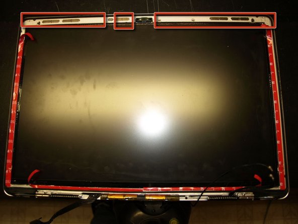
Tooling holes on the left and right upper corners.
-
Camera.
-
EMI Pad
-
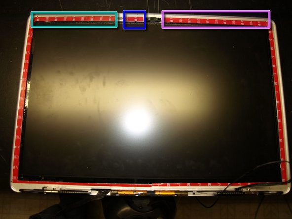
On the flange of the display assembly:
-
Apply the 6mm x 120mm strip, red side up, to the area on the flange between the EMI pad and the adhesive strip on the left side.
-
Apply the 6mm x 30mm strip, red side up, to the area on the flange between the EMI pad and the camera.
-
Apply the 6mm x 155mm strip, red side up, to the area on the flange between the camer and the adhesive strip on the right side.
-
-
Dieser Schritt ist noch nicht übersetzt. Hilf mit, ihn zu übersetzen!
-
While applying pressure with the flat side of the spudger, drag the spudger across all of the attached adhesive strips.
-
-
Dieser Schritt ist noch nicht übersetzt. Hilf mit, ihn zu übersetzen!
-
On the upper corner of the adhesive on the left side of the display assembly.
-
Slip an X-acto knife between the red backing and
-
Use the X-acto knife to peel enough of the backing so that it can be grabbed with fingers.
-
Peel about one inch of the red backing and fold it to the inside.
-
Do the same for the adhesive on the right side and both adhesive strips on the bottom of the display.
-
For the three strips on the top of the display, peel all of the adhesive backing off.
-
-
Dieser Schritt ist noch nicht übersetzt. Hilf mit, ihn zu übersetzen!
-
Carefully align the bezel tooling pin into in the tooling holes at the top of the display assembly. Set the bezel in place and apply pressure.
-
Pull the rest of the red backing strips to expose the adhesive to the rest of the bezel.
-
While applying pressure with the flat side of the spudger, rub around the entire bezel to ensure the adhesive sets properly.
-
-
Dieser Schritt ist noch nicht übersetzt. Hilf mit, ihn zu übersetzen!
-
Place binder clips around the bezel to hold it in place. Use cardboard under the clips to keep from scratching the display assembly.
-


Rückgängig: Ich habe diese Anleitung nicht absolviert.
4 weitere Nutzer:innen haben diese Anleitung absolviert.

Ein Kommentar
Just finished this and here's my 2 cents:
1) If you use guitar picks to pry the bezel out you cant do it inside out. That means no need to mess with that rubber band that goes around it. Also means it wont look as bad (bowed) once you're done removing it;
2) It is aluminium so you can always un-bend the thing and straighten it up just be careful;
3) I realise it probably wasn't available at the time this guide was made but you can use the tape designed to hold thin edged iMac's displays. That's what I did anyway and it worked like a charm no need to bind anything (had one set of those tapes laying around for future project so that was easy to get :P).
Hope that helps :)