Diese Version enthält möglicherweise inkorrekte Änderungen. Wechsle zur letzten geprüften Version.
Was du brauchst
-
-
Entferne die folgenden 10 Schrauben, die das Gehäuseunterteil mit dem Deckel verbinden:
-
Drei 13.5 mm Kreuzschlitzschrauben
-
Sieben 3 mm Kreuzschlitzschrauben
-
-
-
Zwänge deine Finger zwischen das Gehäuseunterteil und die Lüftungsschlitze und ziehe das Unterteil nach oben, um die Clips zu lösen, mit denen das Gehäuseunterteil am Deckel befestigt ist.
-
Entferne das Gehäuseunterteil.
-
-
-
Falls vorhanden, ziehe die kleine Plastiklasche am Akkustecker gegen die Vorderkante des Geräts. Bei Modellen von Ende 2011 hat der Stecker keine Lasche und ist einfach direkt im Motherboard eingesteckt. In diesem Fall ziehe den Stecker gerade nach oben, um ihn zu entfernen.
-
-
Dieser Schritt ist noch nicht übersetzt. Hilf mit, ihn zu übersetzen!
-
Use the tip of a spudger to push the small plastic cable retainer away from the camera cable socket for enough clearance to remove the camera cable.
-
-
Dieser Schritt ist noch nicht übersetzt. Hilf mit, ihn zu übersetzen!
-
Pull the camera cable toward the optical drive opening to disconnect it from the logic board.
-
-
Dieser Schritt ist noch nicht übersetzt. Hilf mit, ihn zu übersetzen!
-
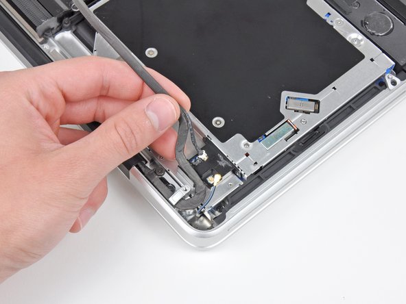
Carefully pull the Bluetooth cable toward the fans to disconnect it from the Bluetooth board.
-
-
-
Dieser Schritt ist noch nicht übersetzt. Hilf mit, ihn zu übersetzen!
-
Use the flat end of a spudger to peel the thin plastic cover off the top and sides of the Bluetooth board housing. For late-2011 models check out the other picture because the connector location is in a totally different location.
-
-
Dieser Schritt ist noch nicht übersetzt. Hilf mit, ihn zu übersetzen!
-
Use the flat end of a spudger to pry the Bluetooth antenna connector up and off its socket on the Bluetooth board.
-
-
Dieser Schritt ist noch nicht übersetzt. Hilf mit, ihn zu übersetzen!
-
De-route the camera cable from the slot molded into the Bluetooth board housing.
-
-
Dieser Schritt ist noch nicht übersetzt. Hilf mit, ihn zu übersetzen!
-
Remove the two 7.1 mm Phillips screws securing the camera cable retainer to the upper case.
-
Remove the camera cable retainer from the upper case.
-
-
Dieser Schritt ist noch nicht übersetzt. Hilf mit, ihn zu übersetzen!
-
Lift the black plastic flap attached to the display data cable retainer and rotate it toward the DC-In side of the MacBook.
-
Pull the display data cable out of its socket.
-
-
Dieser Schritt ist noch nicht übersetzt. Hilf mit, ihn zu übersetzen!
-
Remove the two 7.1 mm Phillips screws securing the display data cable retainer to the upper case.
-
Remove the display data cable retainer.
-
-
Dieser Schritt ist noch nicht übersetzt. Hilf mit, ihn zu übersetzen!
-
Remove the two outer 6.8 mm T6 Torx screws from each of the two display brackets (four screws total).
-
-
Dieser Schritt ist noch nicht übersetzt. Hilf mit, ihn zu übersetzen!
-
While holding the display and upper case together with your left hand, remove the remaining T6 Torx screw from the lower display bracket.
-
-
Dieser Schritt ist noch nicht übersetzt. Hilf mit, ihn zu übersetzen!
-
Remove the last remaining T6 Torx screw securing the display to the upper case.
-
-
Dieser Schritt ist noch nicht übersetzt. Hilf mit, ihn zu übersetzen!
-
Grab the upper case with your right hand and rotate it slightly toward the top of the display so the upper display bracket clears the edge of the upper case.
-
Rotate the display slightly away from the upper case.
-
Lift the display up and away from the upper case, minding any brackets or cables that may get caught.
-


Rückgängig: Ich habe diese Anleitung nicht absolviert.
41 weitere Nutzer:innen haben diese Anleitung absolviert.

7 Kommentare
This guide was a bit difficult to follow because the photos didn't represent 'exactly' what I was seeing. I was able to find the corresponding connections.
The trouble I'm having is the guide seems to end a few steps too soon. I still have a display inside the upper shell, the piece with the Apple logo. I'm very concerned for the well-being of the 'old' pieces in question. I have to save the upper case piece while extracting the display.
Any ideas please?
The title is misleading, and only covers the upper shell removal. I believe your issue is that you want to replace the display panel only, and not the enclosure or camera device. In most cases, however, technicians will simply counsel replacement of the entire upper shell, as replacing inner display components will rack up service hours and end up costing the equivalent of a new shell.
From an iFixit perspective, however, this is moot. You could find a display panel component on ebay, and do the work. I hope you found a more in-depth guide.
According to comments from iFixit on the teardown (MacBook Pro 17" Unibody Teardown), they don’t consider the upper case assembly to be repairable. See comments on step 23 of the teardown.
If anyone has been able to open and close the upper case without damaging it, please share the procedure with the rest of us!
shamino -
17” 2011 Macbook Pro 2.5 (BTO) has a different section at the left hand side, the part where the cables for the wireless hook up. Pay attention to the layout and think before untying any screws. The board that hooks up the wireless is “in” a separate bridge, installed next to the DVD writer with independent screws for suspension.