Diese Version enthält möglicherweise inkorrekte Änderungen. Wechsle zur letzten geprüften Version.
Was du brauchst
-
-
Erwärme die Kanten des Bildschirms mit Heizkissen oder Heißluftpistole, um den Klebstoff aufzuweichen. Diese Stellen befinden sich ungefähr 2-3 cm von den Kanten des Geräts entfernt.
-
-
-
Verwende ein Plastik-Öffnungswerkzeug und einen Saugheber, um das Display anzuheben und setze vorsichtig eine Kante des Öffnungswerkzeugs unter die Ecke des Displays.
-
Arbeite dich langsam mit dem Werkzeug rund um die gesamte Kante des Bildschirms herum.
-
-
-
-
Stecke die orangen Kabel aus, die das Display mit der Hauptplatine verbinden, indem du an den kleinen Laschen ziehst. Verwende den Nylon-Spudger, um die Kabel zu lösen.
-
Lass den Kleber abkühlen, bevor er mit anderen Oberflächen in Kontakt kommt.
-
-
Dieser Schritt ist noch nicht übersetzt. Hilf mit, ihn zu übersetzen!
-
Make sure that the front-facing camera is completely disconnected, and then remove the plastic bracket.
-
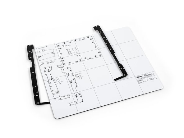
Remove the 22 screws on the bezel.
-
Remove the left and right brackets; the left has 16 screws and the right has 15 screws.
-
-
Dieser Schritt ist noch nicht übersetzt. Hilf mit, ihn zu übersetzen!
-
Once the brackets are removed, set them aside.
-
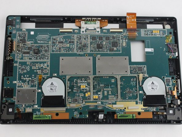
Remove the 25 screws of varying sizes that attach the motherboard to the back plate.
-
-
Dieser Schritt ist noch nicht übersetzt. Hilf mit, ihn zu übersetzen!
-
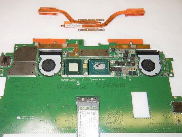
On the underside of the motherboard locate the heat shield which is located between the two fans near the top of the motherboard.
-
Remove the heat shield using an opening pick by lifting along the edges.
-
Remove all four Torx T5 screws located in each corner of the heat sink mounting frame.
-
Carefully lift off the heat sinks from the motherboard.
-


Rückgängig: Ich habe diese Anleitung nicht absolviert.
Ein:e weitere:r Nutzer:in hat diese Anleitung absolviert.

Team

The Citadel Military College of South Carolina, Team S3-G11, Eggleston Fall 2019 Mitglied von The Citadel Military College of South Carolina, Team S3-G11, Eggleston Fall 2019
CMCSC-EGGLESTON-F19S3G11
3 Mitglieder
4 Anleitungen geschrieben