Diese Version enthält möglicherweise inkorrekte Änderungen. Wechsle zur letzten geprüften Version.
Was du brauchst
-
Dieser Schritt ist noch nicht übersetzt. Hilf mit, ihn zu übersetzen!
-
Use a Phillips #000 screwdriver to remove the four screws around the perimeter of the LCD panel.
-
-
Dieser Schritt ist noch nicht übersetzt. Hilf mit, ihn zu übersetzen!
-
Using a fingernail or the flat edge of a spudger inserted into the seam, separate the LCD bevel from the main panel body.
-
-
-
Dieser Schritt ist noch nicht übersetzt. Hilf mit, ihn zu übersetzen!
-
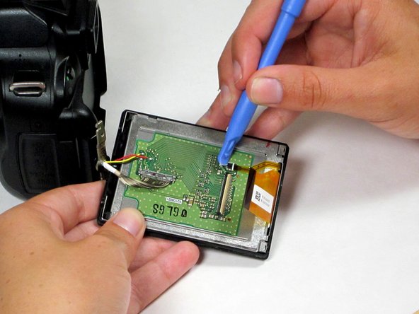
Use a spudger to remove the ribbon cables on the LCD's circuit board by flipping up their plastic lock-bars and removing gently pulling them out of their ports.
-
-
Dieser Schritt ist noch nicht übersetzt. Hilf mit, ihn zu übersetzen!
-
Use a spudger to disconnect the 16-pin cable by gently pulling it upward, away from the circuit board, until it is removed from its port.
-
-
Dieser Schritt ist noch nicht übersetzt. Hilf mit, ihn zu übersetzen!
-
Desolder the 3 wires (red, yellow, and black) connecting the LCD board to the main camera body.
-
-
Dieser Schritt ist noch nicht übersetzt. Hilf mit, ihn zu übersetzen!
-
The LCD assembly can now be fully separated from the main camera body.
-
Remove the plastic bezel and metal bracket from the LCD itself to complete the removal process.
-


Rückgängig: Ich habe diese Anleitung nicht absolviert.
9 weitere Nutzer:innen haben diese Anleitung absolviert.
Team

Cal Poly, Team 10-54, Amido Spring 2014 Mitglied von Cal Poly, Team 10-54, Amido Spring 2014
CPSU-AMIDO-S14S10G54
4 Mitglieder
5 Anleitungen geschrieben
6 Kommentare
Thanks for this Liz.
Removing the broken LCD from my Nikon D5100 seems like something I can do now!
I am unsure ?how to do the soldering bit to attach the new LCD, ?where to attach the wires...
Any help is welcome
I was able to fix it, thanks to you guys. But the colors that came on the, LCD are weird. At least I can see the image.
It’s very possible that applying the soldering iron to the board, while still attached to the back, caused the LCD to lose its color alignment and darken the display. I made the same mistake.
Franky -
I am having trouble reconnecting the 16-pin cable to the circuit board. Do you have any tips?