Einleitung
Wenn dein Nintendo GameCube nicht mehr funktioniert, d.h. nicht mehr in der Lage ist, deine Discs zu lesen, kannst du mithilfe dieser Anleitung die optische Laserlinse des Nintendo GameCube ersetzen.
Bevor du anfängst, schalte deinen GameCube vollständig aus und trenne ihn von jeglicher externen Stromquelle.
Was du brauchst
-
-
Drehe den GameCube um, so dass die Unterseite des Gerätes nach oben zeigt.
-
Entferne alle vier Schrauben mit einem 4,5 mm Gamebit Schraubendreher.
-
-
-
Wenn alle vier Schrauben entfernt wurden - das Gerät liegt weiterhin mit der Unterseite nach oben - kann man das Geräteunterteil vorsichtig nach oben ziehen und vom oberen Gehäuseteil trennen. Das Unterteil wird nun mit dem Bauteilinneren nach oben auf einer Unterlage abgelegt.
-
Lege das Unterteil mit der Innenseite nach oben.
-
-
-
Drücke leicht auf die Klammern an den Seiten der Gehäuserückwand.
-
Entferne die Rückwand vorsichtig vom Gehäuse des GameCube.
-
-
-
Bei abgenommener Rückwand können nun vorsichtig die Controller-Ports auf der Vorderseite des Geräts abgesteckt werden.
-
-
-
Entferne die zwei PH2-Kreuzschlitzschrauben auf der Rückseite des Steueranschlusses.
-
Trenne nun vorsichtig die graue Gehäuseverkleidung des Steueranschlusses von der Platine.
-
-
-
Auf der linken Seite der Einheit befindet sich der Lüfter inkl. Gehäuse.
-
Entferne nun vorsichtig die zwei Schrauben, die das Lüftergehäuse mit der Einheit verbinden.
-
-
-
-
Entferne die vier Kreuzschlitzschrauben #1, mit denen die Erdungsfedern befestigt sind.
-
Nimm nun vorsichtig die Erdungsfedern heraus.
-
-
-
Das optische Laufwerk ist auf einer Metallplatte befestigt.
-
Entferne nun die zwölf Schrauben, die rund um das optische Laufwerk angebracht sind.
-
-
-
Trenne nun vorsichtig die Laufwerks-Baugruppe von der GameCube Einheit.
-
Die Laufwerks-Baugruppe ist durch eine Nut an der darunterliegenden Hauptplatine befestigt. Möglicherweise braucht man etwas Kraft, um die Baugruppe vorsichtig zu lösen.
-
Die Metallplatte und das eigentliche optische Laufwerk bleiben miteinander verbunden.
-
-
-
Jetzt sollte das optische Laufwerk vom GameCube getrennt sein.
-
Drehe das optische Laufwerk mit der Unterseite nach oben.
-
Entferne die sechs Kreuzschlitzschrauben #1.
-
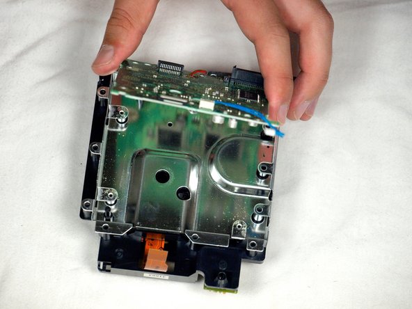
Hebe die Metallplatte vorsichtig an und entferne sie.
-
-
-
Entferne das blaue Kabel durch vorsichtiges Ziehen.
-
Trenne das braune Kabel ab. Ziehe dazu vorsichtig die schwarze Lasche vom weißen Kunststoff ab. Dadurch wird das braune Kabel gelockert, so dass es vorsichtig von der Lasche weggeschoben werden kann.
-
Entferne die vier Kreuzschlitzschrauben #1, die die Leiterplatte mit der optischen Laufwerksbaugruppe verbinden.
-
Die vierte Schraube befindet sich hinter dem Schraubendreher in der dritten Abbildung.
-
-
-
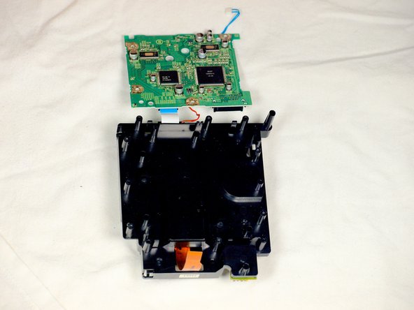
Löse die kleine Raste, mit der die Leiterplatte befestigt ist.
-
Entferne vorsichtig die Leiterplatte (das große grüne Quadrat), wie in den drei Abbildungen gezeigt.
-
Rotes Kabel
-
Weißes Flachbandkabel
-
-
-
Löse mit einem Schlitzschraubendreher vorsichtig die vier Kunststoffklammern, mit denen die Laufwerksbaugruppe zusammengehalten wird.
-
-
-
Hebe die Metallplatte vorsichtig von der Laufwerksbaugruppe ab.
-
Drehe dann die beiden Hälften der Laufwerksbaugruppe um.
-
-
-
Löse mit einem Schlitzschraubendreher die beiden Clips an der hinteren Hälfte der Laufwerksbaugruppe.
-
Der letzte Clip braucht nicht gelöst zu werden; die obere Hälfte der Laufwerksbaugruppe gleitet von der unteren Hälfte weg.
-
Nimm die obere Hälfte der Laufwerksbaugruppe aus der Basis heraus.
-
-
-
Sobald die obere Hälfte der Laufwerksbaugruppe abgenommen ist, drehe sie mit der Unterseite nach oben.
-
Entferne mit einem PH1-Kreuzschlitzschraubendreher vorsichtig die drei letzten Schrauben, die sich in der Nähe der Leisten der Linsenbaugruppe befinden.
-
Ziehe die Linsenbaugruppe heraus und entferne sie.
-
-
-
Wenn die Lasereinheit vom optischen Laufwerk abgetrennt ist, dann setze die neue Lasereinheit in das Laufwerk ein und folge den Schritten in umgekehrter Reihenfolge.
-


Um dein Gerät wieder zusammenzusetzen, folge den Schritten in umgekehrter Reihenfolge.
Um dein Gerät wieder zusammenzusetzen, folge den Schritten in umgekehrter Reihenfolge.
Rückgängig: Ich habe diese Anleitung nicht absolviert.
24 weitere Nutzer:innen haben diese Anleitung absolviert.
Besonderer Dank geht an diese Übersetzer:innen:
100%

Diese Übersetzer:innen helfen uns, die Welt zu reparieren! Wie kann ich mithelfen?
Hier starten ›

Team

Cal Poly, Team 6-2, Maness Fall 2009 Mitglied von Cal Poly, Team 6-2, Maness Fall 2009
CPSU-MANESS-F09S6G2
4 Mitglieder
45 Anleitungen geschrieben