Diese Version enthält möglicherweise inkorrekte Änderungen. Wechsle zur letzten geprüften Version.
Was du brauchst
-
-
Die vier 6,4 mm Schrauben auf der Rückseite mit einem Phillips #00 Schraubendreher entfernen.
-
-
-
Öffne den Zubehörslot mit einem Fingernagel oder Spudger.
-
Entferne die zwei 5,4 mm Schrauben mit einem Phillips #00 Schraubendreher.
-
-
-
Trenne die Front- und Rückseite, indem du ein Plastic Opening Tool an der Seite des Gerätes einführst.
-
Vorsichtig um das Gerät herum gehen und aufhebeln.
-
-
-
Vorsichtig die beiden Seiten trennen und auf die Batterie- und Touchscreen-Controller-Verbindungen, welche die Seiten zusammenhalten, achten.
-
-
Dieser Schritt ist noch nicht übersetzt. Hilf mit, ihn zu übersetzen!
-
Using the pointy end of the spudger, disconnect the three antenna cable connectors on top of the wireless card.
-
Deroute the antenna cables so that they are out of the wireless card casing. Rest the wires out of the way.
-
-
Dieser Schritt ist noch nicht übersetzt. Hilf mit, ihn zu übersetzen!
-
Hook the spudger beneath the tab on the wireless card casing and release the tab.
-
Peel up and remove the wireless card casing.
-
-
Dieser Schritt ist noch nicht übersetzt. Hilf mit, ihn zu übersetzen!
-
Remove the two 4.4mm Phillips #00 screws on the wireless card.
-
Pull out the wireless card.
-
-
Dieser Schritt ist noch nicht übersetzt. Hilf mit, ihn zu übersetzen!
-
Pry up the right shoulder button casing with a spudger and set it aside.
-
-
Dieser Schritt ist noch nicht übersetzt. Hilf mit, ihn zu übersetzen!
-
Remove the translucent, plastic right shoulder button cover.
-
-
Dieser Schritt ist noch nicht übersetzt. Hilf mit, ihn zu übersetzen!
-
Release the right shoulder button flex cable socket by using a spudger to gently pry open the tab.
-
Using tweezers, slide the flex cable out of the socket.
-
-
Dieser Schritt ist noch nicht übersetzt. Hilf mit, ihn zu übersetzen!
-
Using a spudger, gently peel up the right shoulder button from the light adhesive connecting it to casing.
-
-
Dieser Schritt ist noch nicht übersetzt. Hilf mit, ihn zu übersetzen!
-
Using the pointy end of a spudger, detach the antenna cable on the right button board.
-
Remove the antenna cable.
-
-
Dieser Schritt ist noch nicht übersetzt. Hilf mit, ihn zu übersetzen!
-
Using a spudger, pry up and release the ZIF socket on the right button board.
-
Gently pull the flex cable out of the socket. Rest the flex cable out of the way.
-
-
Dieser Schritt ist noch nicht übersetzt. Hilf mit, ihn zu übersetzen!
-
Release the tab on the small flex cable socket by prying up the tab with a spudger.
-
Using tweezers, gently pull the flex cable out of the socket. Rest the flex cable out of the way.
-
-
-
Dieser Schritt ist noch nicht übersetzt. Hilf mit, ihn zu übersetzen!
-
Remove the two 5.0mm Phillips #00 screws from the metal bracket securing the right button board to the motherboard.
-
Remove the metal bracket, using a spudger as necessary to lift it out.
-
-
Dieser Schritt ist noch nicht übersetzt. Hilf mit, ihn zu übersetzen!
-
Use a spudger to free the right button board by prying up from the bottom right corner of board.
-
Gently lift the right button board out.
-
-
Dieser Schritt ist noch nicht übersetzt. Hilf mit, ihn zu übersetzen!
-
Pry up the left shoulder button casing with a spudger.
-
Remove the left shoulder button casing.
-
-
Dieser Schritt ist noch nicht übersetzt. Hilf mit, ihn zu übersetzen!
-
Remove the translucent, plastic left shoulder button cover.
-
-
Dieser Schritt ist noch nicht übersetzt. Hilf mit, ihn zu übersetzen!
-
Release the left shoulder button flex cable socket by using a spudger to pry open the tab.
-
Using tweezers, slide the flex cable out of the socket. Do not pull on the black tab! Instead, pull the thin flex cable away from the connector (to the left in this image).
-
-
Dieser Schritt ist noch nicht übersetzt. Hilf mit, ihn zu übersetzen!
-
Using a spudger, gently peel up the left shoulder button from the light adhesive connecting it to casing.
-
-
Dieser Schritt ist noch nicht übersetzt. Hilf mit, ihn zu übersetzen!
-
Using a spudger, lift and release the tab on the ZIF socket sitting on the SIM card reader.
-
Carefully pull the flex cable out of the ZIF socket, and rest it out of the way.
-
-
Dieser Schritt ist noch nicht übersetzt. Hilf mit, ihn zu übersetzen!
-
Use a spudger to release the tab between the SIM card reader and the back casing assembly.
-
Lift the SIM card reader off the back casing assembly.
-
-
Dieser Schritt ist noch nicht übersetzt. Hilf mit, ihn zu übersetzen!
-
Release the plastic tab on the small flex cable socket by prying it up with a spudger.
-
Using tweezers, gently remove the small flex cable from the socket, and rest it out of the way.
-
-
Dieser Schritt ist noch nicht übersetzt. Hilf mit, ihn zu übersetzen!
-
Use a spudger to lift up the tab on the large ZIF socket.
-
Gently pull the flex cable out of the ZIF socket, and rest it out of the way.
-
-
Dieser Schritt ist noch nicht übersetzt. Hilf mit, ihn zu übersetzen!
-
Disconnect the white Wi-Fi antenna cable with a spudger.
-
Remove the Wi-Fi antenna cable.
-
-
Dieser Schritt ist noch nicht übersetzt. Hilf mit, ihn zu übersetzen!
-
Using a Phillips #00 screwdriver, remove the six screws on the two metal brackets:
-
Two 5.0mm, blue screws on the L-bracket securing the upper left button board to the motherboard.
-
Four 5.0mm, blue screws on the square bracket securing the lower left button board to the motherboard.
-
-
Dieser Schritt ist noch nicht übersetzt. Hilf mit, ihn zu übersetzen!
-
Starting from the upper left corner, use a spudger to pry up and remove the left button board.
-
-
Dieser Schritt ist noch nicht übersetzt. Hilf mit, ihn zu übersetzen!
-
Using the pointy end of a spudger, pry up and release the GPS antenna cable from the motherboard.
-
Remove the GPS antenna cable.
-
-
Dieser Schritt ist noch nicht übersetzt. Hilf mit, ihn zu übersetzen!
-
Release the camera flex cable socket by prying up on the tab with a spudger.
-
-
Dieser Schritt ist noch nicht übersetzt. Hilf mit, ihn zu übersetzen!
-
Using a spudger, gently pry up on the camera.
-
Work your way under the camera and along the camera flex cable, using the spudger to peel away the adhesive, freeing the camera.
-
-
Dieser Schritt ist noch nicht übersetzt. Hilf mit, ihn zu übersetzen!
-
Carefully lift and remove the camera, sliding the flex cable out of the open connector socket.
-
-
Dieser Schritt ist noch nicht übersetzt. Hilf mit, ihn zu übersetzen!
-
Using a Phillips #00 screwdriver, remove the 6.3mm screw beneath the camera.
-
Lift and remove the metal camera bracket.
-
-
Dieser Schritt ist noch nicht übersetzt. Hilf mit, ihn zu übersetzen!
-
With the help of a spudger, lift and release the tab on the blue flex cable socket.
-
-
Dieser Schritt ist noch nicht übersetzt. Hilf mit, ihn zu übersetzen!
-
Using tweezers, gently pull the blue power flex cable out of the socket; rest it out of the way.
-
-
Dieser Schritt ist noch nicht übersetzt. Hilf mit, ihn zu übersetzen!
-
Using a Phillips #00 screwdriver, remove the two pink, 4.4mm screws securing the motherboard.
-
-
Dieser Schritt ist noch nicht übersetzt. Hilf mit, ihn zu übersetzen!
-
Gently peel the rubber tab of the game port cover off the plastic casing pins.
-
Remove the game port cover.
-
-
Dieser Schritt ist noch nicht übersetzt. Hilf mit, ihn zu übersetzen!
-
Gently peel the rubber tab of the accessory port cover off the plastic casing pins.
-
Remove the accessory port cover.
-
-
Dieser Schritt ist noch nicht übersetzt. Hilf mit, ihn zu übersetzen!
-
Starting at the upper right hand corner, use a spudger to gently lift the motherboard out of the casing assembly.
-
-
Dieser Schritt ist noch nicht übersetzt. Hilf mit, ihn zu übersetzen!
-
Lift the motherboard out and identify the OLED connector still attaching the motherboard to the casing.
-
Holding the Vita on its side, use a spudger to gently pry off the OLED connector from the motherboard.
-
-
Dieser Schritt ist noch nicht übersetzt. Hilf mit, ihn zu übersetzen!
-
Completely separate the motherboard from the case. Remove the case.
-
-
Dieser Schritt ist noch nicht übersetzt. Hilf mit, ihn zu übersetzen!
-
Starting at the right side, gently lift and remove the black casing that once held the camera.
-
-
Dieser Schritt ist noch nicht übersetzt. Hilf mit, ihn zu übersetzen!
-
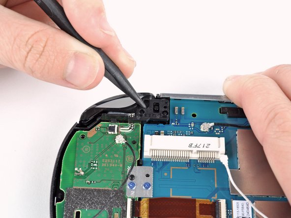
Using a spudger, release the tab on the ZIF connector located above the two screw posts where the wireless card once was.
-
-
Dieser Schritt ist noch nicht übersetzt. Hilf mit, ihn zu übersetzen!
-
Gently pull the flex cable out of the ZIF connector, and remove it.
-
-
Dieser Schritt ist noch nicht übersetzt. Hilf mit, ihn zu übersetzen!
-
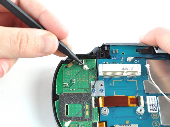
Release the tab on the large ZIF connector on the right side of the motherboard by lifting the tab with a spudger.
-
-
Dieser Schritt ist noch nicht übersetzt. Hilf mit, ihn zu übersetzen!
-
Gently pull the flex cable out of the ZIF connector, and remove it.
-
-
Dieser Schritt ist noch nicht übersetzt. Hilf mit, ihn zu übersetzen!
-
Using a spudger, release the small ZIF connector on the right side of the motherboard.
-
-
Dieser Schritt ist noch nicht übersetzt. Hilf mit, ihn zu übersetzen!
-
Gently pull the flex cable out of the small ZIF connector, and remove it.
-
-
Dieser Schritt ist noch nicht übersetzt. Hilf mit, ihn zu übersetzen!
-
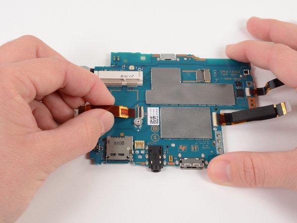
Flip the motherboard over.
-
With the help of a spudger, pry up and release the tab of the rear camera flex cable connector.
-
-
Dieser Schritt ist noch nicht übersetzt. Hilf mit, ihn zu übersetzen!
-
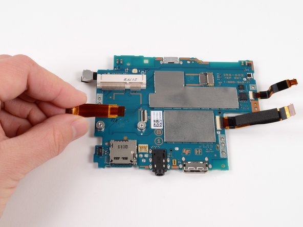
Gently pull the rear camera out of the connector and remove it.
-


Rückgängig: Ich habe diese Anleitung nicht absolviert.
41 weitere Nutzer:innen haben diese Anleitung absolviert.


11 Kommentare
in steps 2&3, bottom is top and top is bottom
it should be noted that the memory card should always be taken out before separating the case. I just broke my memory card slot by having a card in there while I was opening the case, there's a tiny bit of overhang that will pull the slot off the motherboard.
Okay My original Motherboard power connector broke. So nothing was wrong with it except the Power connector.
My first buy of the Motherboard screen connector broke off.
The Replacement works well, however the Touch input isn't working, unless I restore the device. After a certain amount of time it becomes unresponsive.
Do anyone have a fix before I get a 3rd replacement.