Diese Version enthält möglicherweise inkorrekte Änderungen. Wechsle zur letzten geprüften Version.
Was du brauchst
-
-
Die vier 6,4 mm Schrauben auf der Rückseite mit einem Phillips #00 Schraubendreher entfernen.
-
-
-
Öffne den Zubehörslot mit einem Fingernagel oder Spudger.
-
Entferne die zwei 5,4 mm Schrauben mit einem Phillips #00 Schraubendreher.
-
-
-
Trenne die Front- und Rückseite, indem du ein Plastic Opening Tool an der Seite des Gerätes einführst.
-
Vorsichtig um das Gerät herum gehen und aufhebeln.
-
-
-
Vorsichtig die beiden Seiten trennen und auf die Batterie- und Touchscreen-Controller-Verbindungen, welche die Seiten zusammenhalten, achten.
-
-
-
Dieser Schritt ist noch nicht übersetzt. Hilf mit, ihn zu übersetzen!
-
Using the pointy end of the spudger, disconnect the three antenna cable connectors on top of the wireless card.
-
Deroute the antenna cables so that they are out of the wireless card casing. Rest the wires out of the way.
-
-
Dieser Schritt ist noch nicht übersetzt. Hilf mit, ihn zu übersetzen!
-
Hook the spudger beneath the tab on the wireless card casing and release the tab.
-
Peel up and remove the wireless card casing.
-
-
Dieser Schritt ist noch nicht übersetzt. Hilf mit, ihn zu übersetzen!
-
Remove the two 4.4mm Phillips #00 screws on the wireless card.
-
Pull out the wireless card.
-
-
Dieser Schritt ist noch nicht übersetzt. Hilf mit, ihn zu übersetzen!
-
Pry up the right shoulder button casing with a spudger and set it aside.
-
-
Dieser Schritt ist noch nicht übersetzt. Hilf mit, ihn zu übersetzen!
-
Remove the translucent, plastic right shoulder button cover.
-
-
Dieser Schritt ist noch nicht übersetzt. Hilf mit, ihn zu übersetzen!
-
Release the right shoulder button flex cable socket by using a spudger to gently pry open the tab.
-
Using tweezers, slide the flex cable out of the socket.
-
-
Dieser Schritt ist noch nicht übersetzt. Hilf mit, ihn zu übersetzen!
-
Using a spudger, gently peel up the right shoulder button from the light adhesive connecting it to casing.
-
-
Dieser Schritt ist noch nicht übersetzt. Hilf mit, ihn zu übersetzen!
-
Using the pointy end of a spudger, detach the antenna cable on the right button board.
-
Remove the antenna cable.
-
-
Dieser Schritt ist noch nicht übersetzt. Hilf mit, ihn zu übersetzen!
-
Using a spudger, pry up and release the ZIF socket on the right button board.
-
Gently pull the flex cable out of the socket. Rest the flex cable out of the way.
-
-
Dieser Schritt ist noch nicht übersetzt. Hilf mit, ihn zu übersetzen!
-
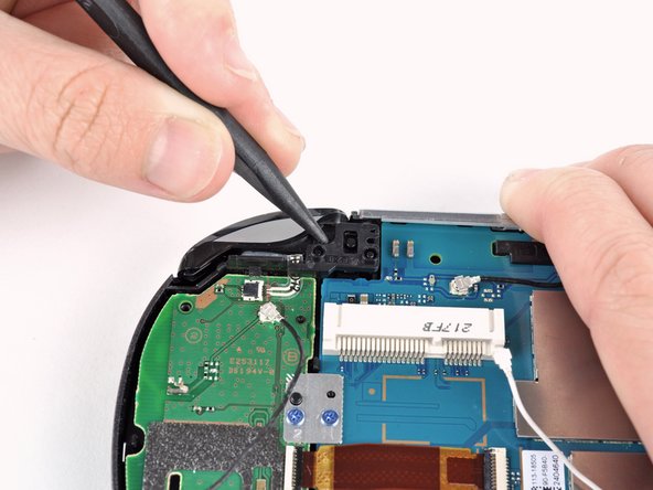
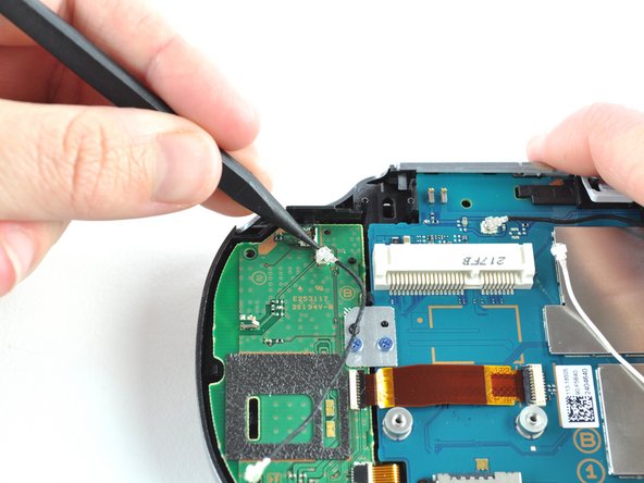
Release the tab on the small flex cable socket by prying up the tab with a spudger.
-
Using tweezers, gently pull the flex cable out of the socket. Rest the flex cable out of the way.
-
-
Dieser Schritt ist noch nicht übersetzt. Hilf mit, ihn zu übersetzen!
-
Remove the two 5.0mm Phillips #00 screws from the metal bracket securing the right button board to the motherboard.
-
Remove the metal bracket, using a spudger as necessary to lift it out.
-
-
Dieser Schritt ist noch nicht übersetzt. Hilf mit, ihn zu übersetzen!
-
Use a spudger to free the right button board by prying up from the bottom right corner of board.
-
Gently lift the right button board out.
-


Rückgängig: Ich habe diese Anleitung nicht absolviert.
Ein:e weitere:r Nutzer:in hat diese Anleitung absolviert.

