Diese Version enthält möglicherweise inkorrekte Änderungen. Wechsle zur letzten geprüften Version.
Was du brauchst
-
Dieser Schritt ist noch nicht übersetzt. Hilf mit, ihn zu übersetzen!
-
Use your thumbs to push the two battery retaining tabs away from the battery.
-
The battery should pop up enough to rotate it toward yourself and lift it out of the lower case.
-
-
Dieser Schritt ist noch nicht übersetzt. Hilf mit, ihn zu übersetzen!
-
Remove the three 2.3 mm Phillips screws securing the memory cover to the lower case.
-
-
Dieser Schritt ist noch nicht übersetzt. Hilf mit, ihn zu übersetzen!
-
Lift the memory cover slightly and pull it toward yourself to remove it from the lower case.
-
-
Dieser Schritt ist noch nicht übersetzt. Hilf mit, ihn zu übersetzen!
-
Remove the following ten screws:
-
Two 14.7 mm shouldered Phillips.
-
Three 12.3 mm Phillips.
-
One 3.8 mm T8 Torx.
-
One 6.8 mm T8 Torx.
-
Three 1.3 mm Phillips.
-
-
Dieser Schritt ist noch nicht übersetzt. Hilf mit, ihn zu übersetzen!
-
Use your fingernails to separate the ZIF cable lock away from its socket. (Move the two brown bits down 1mm)
-
-
Dieser Schritt ist noch nicht übersetzt. Hilf mit, ihn zu übersetzen!
-
Use the tip of a spudger to slide the trackpad ribbon cable out of its socket.
-
-
Dieser Schritt ist noch nicht übersetzt. Hilf mit, ihn zu übersetzen!
-
Remove the four 3.4 mm Phillips screws from the PC card side of the PowerBook.
-
-
Dieser Schritt ist noch nicht übersetzt. Hilf mit, ihn zu übersetzen!
-
Remove the four 3.4 mm Phillips screws from the DVI connector side of the PowerBook.
-
-
Dieser Schritt ist noch nicht übersetzt. Hilf mit, ihn zu übersetzen!
-
Depress the display latch release button and open your display.
-
-
Dieser Schritt ist noch nicht übersetzt. Hilf mit, ihn zu übersetzen!
-
Starting near the display, lift the upper case straight up off the lower case, minding any cables that may get caught.
-
-
Dieser Schritt ist noch nicht übersetzt. Hilf mit, ihn zu übersetzen!
-
Disconnect the RJ-11 cable from the modem.
-
-
Dieser Schritt ist noch nicht übersetzt. Hilf mit, ihn zu übersetzen!
-
If necessary, remove the strip of tape covering the speaker cables.
-
-
Dieser Schritt ist noch nicht übersetzt. Hilf mit, ihn zu übersetzen!
-
Use your fingernails or the tip of a spudger to separate the ZIF cable lock from its socket.
-
-
Dieser Schritt ist noch nicht übersetzt. Hilf mit, ihn zu übersetzen!
-
Pull the DC-in ribbon cable straight away from its socket.
-
-
Dieser Schritt ist noch nicht übersetzt. Hilf mit, ihn zu übersetzen!
-
Peel the DC-in cable off the adhesive securing it to the lower case.
-
-
Dieser Schritt ist noch nicht übersetzt. Hilf mit, ihn zu übersetzen!
-
If necessary, use the tip of a spudger to remove the small piece of foam tape from the side of the left speaker.
-
De-route the AirPort antenna cables from the channel in the left speaker.
-
-
Dieser Schritt ist noch nicht übersetzt. Hilf mit, ihn zu übersetzen!
-
Remove the single 6.9 mm T8 Torx screw securing the left speaker to the lower case.
-
-
Dieser Schritt ist noch nicht übersetzt. Hilf mit, ihn zu übersetzen!
-
Lift the left speaker from its rear edge and maneuver it out of the lower case, minding the cables sitting in the channel near the front edge of the left speaker.
-
-
Dieser Schritt ist noch nicht übersetzt. Hilf mit, ihn zu übersetzen!
-
Remove the single 6.9 mm T8 Torx screw securing the speaker cable ground loop to the lower case.
-
-
Dieser Schritt ist noch nicht übersetzt. Hilf mit, ihn zu übersetzen!
-
Peel back the piece of foil tape covering the modem cable to free the speaker cable held underneath.
-
-
Dieser Schritt ist noch nicht übersetzt. Hilf mit, ihn zu übersetzen!
-
Pull the speaker cable straight up to disconnect it from the sound card.
-
-
Dieser Schritt ist noch nicht übersetzt. Hilf mit, ihn zu übersetzen!
-
Use the flat end of a spudger to pry the hard drive ribbon cable connector up off the logic board.
-
-
Dieser Schritt ist noch nicht übersetzt. Hilf mit, ihn zu übersetzen!
-
Use the flat end of a spudger to pry the sound card cable connector up off the logic board.
-
-
Dieser Schritt ist noch nicht übersetzt. Hilf mit, ihn zu übersetzen!
-
Use the flat end of a spudger to pry the optical drive cable connector up off the logic board.
-
-
-
Dieser Schritt ist noch nicht übersetzt. Hilf mit, ihn zu übersetzen!
-
Use your fingernails or the tip of a spudger to separate the ZIF cable lock from its socket.
-
-
Dieser Schritt ist noch nicht übersetzt. Hilf mit, ihn zu übersetzen!
-
Pull the PRAM battery & USB board cable out of its socket.
-
-
Dieser Schritt ist noch nicht übersetzt. Hilf mit, ihn zu übersetzen!
-
Use a spudger to de-route the display data cable from the channel in the right speaker.
-
-
Dieser Schritt ist noch nicht übersetzt. Hilf mit, ihn zu übersetzen!
-
Use the tip of a spudger to pry the power button LED window off the right speaker.
-
-
Dieser Schritt ist noch nicht übersetzt. Hilf mit, ihn zu übersetzen!
-
Remove the single T8 6.9 mm Torx screw securing the right speaker to the lower case.
-
-
Dieser Schritt ist noch nicht übersetzt. Hilf mit, ihn zu übersetzen!
-
Lift the right speaker out of the lower case.
-
-
Dieser Schritt ist noch nicht übersetzt. Hilf mit, ihn zu übersetzen!
-
De-route the speaker cable from the clips along the front edge of the logic board.
-
-
Dieser Schritt ist noch nicht übersetzt. Hilf mit, ihn zu übersetzen!
-
Close your PowerBook, minding any cables that may interfere, and flip it over.
-
Disconnect the power cable connector by pulling it straight away from its socket on the logic board.
-
-
Dieser Schritt ist noch nicht übersetzt. Hilf mit, ihn zu übersetzen!
-
Disconnect the battery cable connector straight away from its socket on the logic board.
-
-
Dieser Schritt ist noch nicht übersetzt. Hilf mit, ihn zu übersetzen!
-
Use the flat end of a spudger to pry the AirPort/Bluetooth cable connector up off the logic board.
-
-
Dieser Schritt ist noch nicht übersetzt. Hilf mit, ihn zu übersetzen!
-
Use the flat end of a spudger to pry the modem cable connector up off the logic board.
-
-
Dieser Schritt ist noch nicht übersetzt. Hilf mit, ihn zu übersetzen!
-
Use the flat end of a spudger to pry the PC card cage cable connector up off the logic board.
-
-
Dieser Schritt ist noch nicht übersetzt. Hilf mit, ihn zu übersetzen!
-
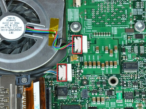
Disconnect both of the following connectors from the logic board:
-
Left fan cable.
-
Inverter cable.
-
-
Dieser Schritt ist noch nicht übersetzt. Hilf mit, ihn zu übersetzen!
-
Remove the following four screws securing the optical drive to the lower case:
-
Three 6.8 mm T8 Torx.
-
One 3.8 mm T8 Torx.
-
Lift the optical drive out of the lower case, minding any cables that may get caught.
-
-
Dieser Schritt ist noch nicht übersetzt. Hilf mit, ihn zu übersetzen!
-
If necessary, remove the piece of tape securing the display data cable to the logic board.
-
-
Dieser Schritt ist noch nicht übersetzt. Hilf mit, ihn zu übersetzen!
-
Pull the display data cable away from its socket to disconnect it from the logic board.
-
-
Dieser Schritt ist noch nicht übersetzt. Hilf mit, ihn zu übersetzen!
-
Disconnect the right fan by pulling its connector away from the socket on the logic board.
-
-
Dieser Schritt ist noch nicht übersetzt. Hilf mit, ihn zu übersetzen!
-
Remove the following 12 screws:
-
Three black 5.7 mm T8 Torx.
-
Three 7 mm T8 Torx with spring washers.
-
Three 6.8 mm T8 Torx.
-
Three 3.8 mm T8 Torx.
-
-
Dieser Schritt ist noch nicht übersetzt. Hilf mit, ihn zu übersetzen!
-
If necessary, use a spudger to pry up the left edge of the logic board to separate the solidified thermal paste from the heat sink.
-
-
Dieser Schritt ist noch nicht übersetzt. Hilf mit, ihn zu übersetzen!
-
Lift the logic board from its left edge and rotate it toward the right side of the lower case.
-
Rotate the logic board until it is nearly vertical, and wiggle it around until it releases from the lower case.
-
-
Dieser Schritt ist noch nicht übersetzt. Hilf mit, ihn zu übersetzen!
-
Use the flat end of a spudger to pry the modem cable connector up off the modem.
-
-
Dieser Schritt ist noch nicht übersetzt. Hilf mit, ihn zu übersetzen!
-
Use a 4 mm nut driver to remove the two nuts securing the modem to the PC card cage.
-
Lift the modem straight up off the studs on the PC card cage.
-
-
Dieser Schritt ist noch nicht übersetzt. Hilf mit, ihn zu übersetzen!
-
Use the tip of a spudger to peel back the small strip of copper tape off the edge of the PC card cage near the side of the lower case.
-
-
Dieser Schritt ist noch nicht übersetzt. Hilf mit, ihn zu übersetzen!
-
Remove the four Phillips screws securing the PC card cage to the lower case.
-
Lift the PC card cage by its center piece and maneuver it out of the lower case.
-
-
Dieser Schritt ist noch nicht übersetzt. Hilf mit, ihn zu übersetzen!
-
Use the tip of a spudger to press the metal pressure connector down through the hole in the AirPort/Bluetooth board and lift it out from the lower case.
-
-
Dieser Schritt ist noch nicht übersetzt. Hilf mit, ihn zu übersetzen!
-
Use the flat end of a spudger to pry the AirPort/Bluetooth board off the adhesive securing it to the lower case.
-
-
Dieser Schritt ist noch nicht übersetzt. Hilf mit, ihn zu übersetzen!
-
If necessary, remove the piece of tape and EMI foam covering the AirPort/Bluetooth antennas.
-
-
Dieser Schritt ist noch nicht übersetzt. Hilf mit, ihn zu übersetzen!
-
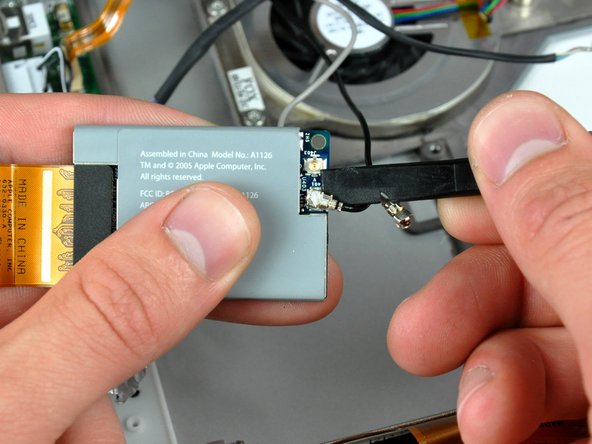
Use the flat end of a spudger to pry both antenna connectors off the AirPort/Bluetooth board.
-
-
Dieser Schritt ist noch nicht übersetzt. Hilf mit, ihn zu übersetzen!
-
Remove four T6 Torx screws from the left display hinge.
-
-
Dieser Schritt ist noch nicht übersetzt. Hilf mit, ihn zu übersetzen!
-
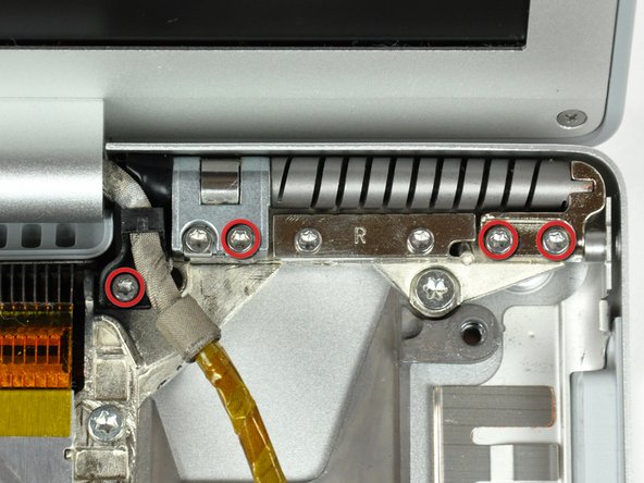
Remove four T6 Torx screws from the right display hinge.
-
-
Dieser Schritt ist noch nicht übersetzt. Hilf mit, ihn zu übersetzen!
-
While supporting the display with one hand, remove the last two T6 Torx screws from the display hinges.
-
-
Dieser Schritt ist noch nicht übersetzt. Hilf mit, ihn zu übersetzen!
-
Lift the display straight up from the lower case, minding any cables that may get caught.
-
-
Dieser Schritt ist noch nicht übersetzt. Hilf mit, ihn zu übersetzen!
-
Remove the two T8 Torx screws securing the DC-in board to the lower case.
-
-
Dieser Schritt ist noch nicht übersetzt. Hilf mit, ihn zu übersetzen!
-
Pull the DC-in board away from the left side of the lower case and set it aside.
-
-
Dieser Schritt ist noch nicht übersetzt. Hilf mit, ihn zu übersetzen!
-
Remove seven Torx T8 screws from the heat sink and fan assembly.
-
-
Dieser Schritt ist noch nicht übersetzt. Hilf mit, ihn zu übersetzen!
-
Lift the heat sink and fan assembly out of the lower case.
-
Lift the heat sink and fan assembly out of the lower case.
-
-
Dieser Schritt ist noch nicht übersetzt. Hilf mit, ihn zu übersetzen!
-
Remove the following four screws:
-
Three 11.1 mm T8 Torx.
-
One 3.9 mm T8 Torx.
-
Lift the hard drive out of the lower case.
-
-
Dieser Schritt ist noch nicht übersetzt. Hilf mit, ihn zu übersetzen!
-
Remove the two T8 Torx screws securing the sound card to the lower case.
-
-
Dieser Schritt ist noch nicht übersetzt. Hilf mit, ihn zu übersetzen!
-
Use the flat end of a spudger to pry the USB sockets away from the left edge of the lower case.
-
-
Dieser Schritt ist noch nicht übersetzt. Hilf mit, ihn zu übersetzen!
-
Lift the sound card slightly out of the lower case, minding the fragile lower portion holding the microphone connector.
-
-
Dieser Schritt ist noch nicht übersetzt. Hilf mit, ihn zu übersetzen!
-
Pull the sound card ribbon cable straight away from its socket on the sound card.
-
-
Dieser Schritt ist noch nicht übersetzt. Hilf mit, ihn zu übersetzen!
-
Use your fingernails to pull the microphone connector straight away from its socket on the sound card.
-
-
Dieser Schritt ist noch nicht übersetzt. Hilf mit, ihn zu übersetzen!
-
Remove the two T8 Torx screws securing the PRAM battery & USB board to the lower case.
-
-
Dieser Schritt ist noch nicht übersetzt. Hilf mit, ihn zu übersetzen!
-
Pull the board away from the side of the lower case to separate the USB socket from the bezel on the lower case.
-
Lift the PRAM battery & USB board out of the lower case.
-
-
Dieser Schritt ist noch nicht übersetzt. Hilf mit, ihn zu übersetzen!
-
Remove the two 8.5 mm T8 Torx screws securing the battery connector to the lower case.
-
-
Dieser Schritt ist noch nicht übersetzt. Hilf mit, ihn zu übersetzen!
-
Pull the battery connector out of its opening in the lower case.
-
Lower case remains.
-