Diese Version enthält möglicherweise inkorrekte Änderungen. Wechsle zur letzten geprüften Version.
Was du brauchst
-
Dieser Schritt ist noch nicht übersetzt. Hilf mit, ihn zu übersetzen!
-
Using a #1 Phillips head screwdriver, remove the three 10mm screws on the back panel.
-
Tilt the back of the top cover forward to remove from chassis.
-
-
Dieser Schritt ist noch nicht übersetzt. Hilf mit, ihn zu übersetzen!
-
Gently pull up on the ribbon cable by the blue tab to remove it from the power supply board.
-
-
-
Dieser Schritt ist noch nicht übersetzt. Hilf mit, ihn zu übersetzen!
-
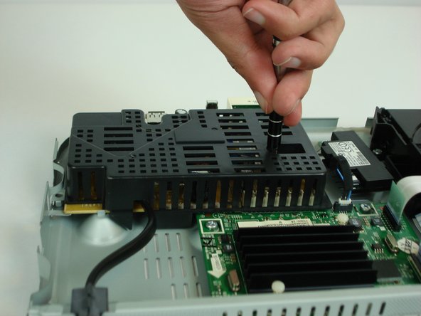
Using a #1 Phillips head screwdriver, remove the two 7.5mm screws on top of the plastic cover and remove the cover.
-
-
Dieser Schritt ist noch nicht übersetzt. Hilf mit, ihn zu übersetzen!
-
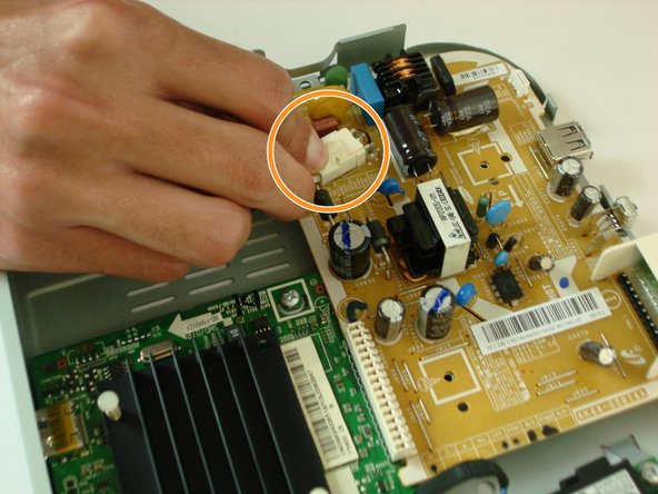
Press down on the plastic retaining clip and pull backwards to remove the AC power connector from the power supply board.
-
-
Dieser Schritt ist noch nicht übersetzt. Hilf mit, ihn zu übersetzen!
-
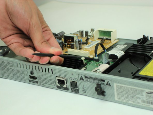
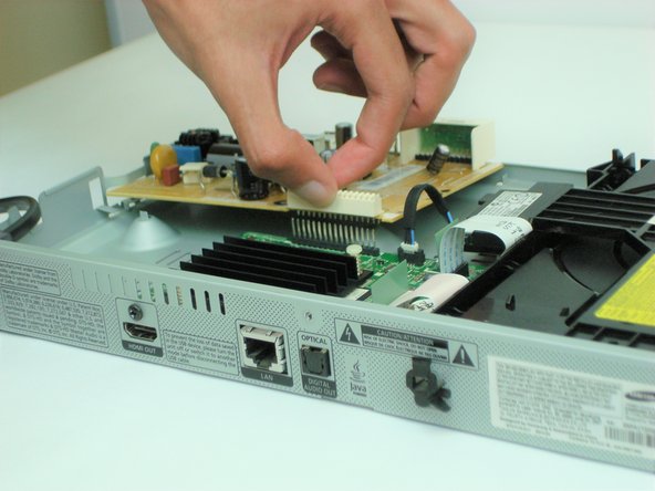
Using the plastic spudger tool, gently pry on either side of main power connector (CON801) to disconnect from main logic board.
-
Tilt the board forward and lift up to remove from the chassis.
-


Team

USF Tampa, Team S1-G21, Cagle Fall 2017 Mitglied von USF Tampa, Team S1-G21, Cagle Fall 2017
USFT-CAGLE-F17S1G21
3 Mitglieder
5 Anleitungen geschrieben