Diese Version enthält möglicherweise inkorrekte Änderungen. Wechsle zur letzten geprüften Version.
Was du brauchst
-
Dieser Schritt ist noch nicht übersetzt. Hilf mit, ihn zu übersetzen!
-
Grasp the end of the stylus and remove it from its slot in the midframe.
-
-
Dieser Schritt ist noch nicht übersetzt. Hilf mit, ihn zu übersetzen!
-
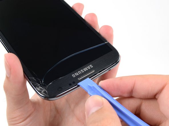
Pry with a plastic opening tool, or your fingernail, in the divot to the left of the rear-facing camera, near the power button.
-
-
Dieser Schritt ist noch nicht übersetzt. Hilf mit, ihn zu übersetzen!
-
Lift the rear case by the corner nearest the divot and remove it from the phone.
-
-
Dieser Schritt ist noch nicht übersetzt. Hilf mit, ihn zu übersetzen!
-
If you have an SD card inserted, use the flat end of a spudger, or your fingernail, to press the microSD card slightly deeper into its slot until you hear a click.
-
After the click, release the card and it will pop out of its slot.
-
Remove the microSD card.
-
-
Dieser Schritt ist noch nicht übersetzt. Hilf mit, ihn zu übersetzen!
-
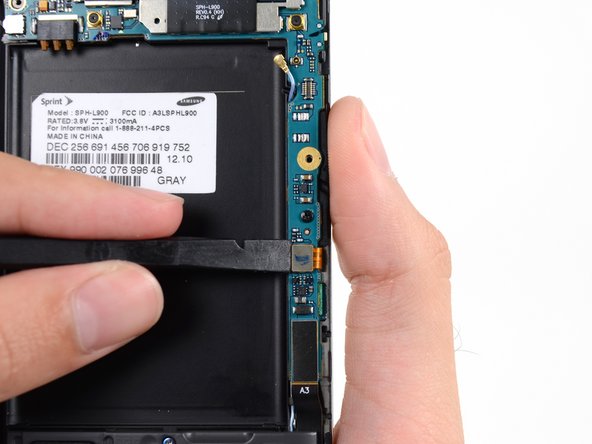
Insert a plastic opening tool, or your finger, into the notch of the battery compartment and lift the battery upward.
-
-
Dieser Schritt ist noch nicht übersetzt. Hilf mit, ihn zu übersetzen!
-
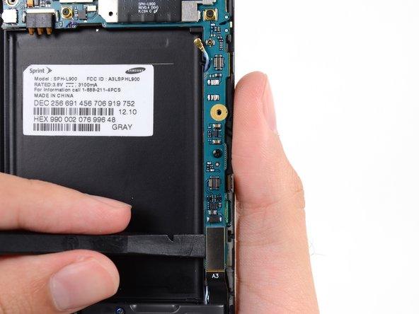
Remove the battery from the midframe.
-
-
Dieser Schritt ist noch nicht übersetzt. Hilf mit, ihn zu übersetzen!
-
Remove the eleven 4.0 mm Phillips #00 screws securing the midframe to the display assembly.
-
-
Dieser Schritt ist noch nicht übersetzt. Hilf mit, ihn zu übersetzen!
-
Insert your plastic opening tool between the midframe and front panel assembly on the side of the phone.
-
Slide the plastic opening tool down the seam.
-
-
Dieser Schritt ist noch nicht übersetzt. Hilf mit, ihn zu übersetzen!
-
Continue to run the plastic opening tool down the seam.
-
-
Dieser Schritt ist noch nicht übersetzt. Hilf mit, ihn zu übersetzen!
-
Carefully pry around the corner with a plastic opening tool.
-
-
Dieser Schritt ist noch nicht übersetzt. Hilf mit, ihn zu übersetzen!
-
Pry along the top of the phone with a plastic opening tool.
-
-
Dieser Schritt ist noch nicht übersetzt. Hilf mit, ihn zu übersetzen!
-
Push the plastic opening tool down to free the corner of the midframe from the display assembly.
-
-
-
Dieser Schritt ist noch nicht übersetzt. Hilf mit, ihn zu übersetzen!
-
Free the clips along the power button side of the phone.
-
Lastly, free the two clips along the top and bottom edge of battery compartment.
-
-
Dieser Schritt ist noch nicht übersetzt. Hilf mit, ihn zu übersetzen!
-
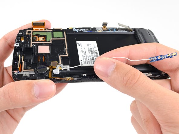
Lift the display assembly out of the midframe.
-
-
Dieser Schritt ist noch nicht übersetzt. Hilf mit, ihn zu übersetzen!
-
Use a spudger to disconnect the vibrator/power button assembly cable connector.
-
Disconnect the antenna cable connector.
-
Disconnect the display cable connector.
-
-
Dieser Schritt ist noch nicht übersetzt. Hilf mit, ihn zu übersetzen!
-
Disconnect the front-facing camera cable connector.
-
Disconnect the headphone jack cable connector.
-
Disconnect the digitizer cable connector.
-
-
Dieser Schritt ist noch nicht übersetzt. Hilf mit, ihn zu übersetzen!
-
Use the spudger to disconnect the antenna cable connector from the motherboard.
-
Disconnect the soft button cable connector.
-
Disconnect the USB board cable connector.
-
-
Dieser Schritt ist noch nicht übersetzt. Hilf mit, ihn zu übersetzen!
-
Remove the 3 mm Phillips #00 screw securing the motherboard to the display assembly.
-
-
Dieser Schritt ist noch nicht übersetzt. Hilf mit, ihn zu übersetzen!
-
Gently remove the motherboard.
-
-
Dieser Schritt ist noch nicht übersetzt. Hilf mit, ihn zu übersetzen!
-
Remove the 3 mm Phillips #00 screw securing the headphone jack assembly to the display assembly.
-
-
Dieser Schritt ist noch nicht übersetzt. Hilf mit, ihn zu übersetzen!
-
Grasp the headphone jack portion of the assembly and lift it out of its groove in the display assembly.
-
-
Dieser Schritt ist noch nicht übersetzt. Hilf mit, ihn zu übersetzen!
-
Gently pull the headphone jack straight up without twisting the cable to remove the earpiece speaker portion from its recess.
-
-
Dieser Schritt ist noch nicht übersetzt. Hilf mit, ihn zu übersetzen!
-
Remove the 3mm Phillips #00 screw from the front-facing camera bracket.
-
-
Dieser Schritt ist noch nicht übersetzt. Hilf mit, ihn zu übersetzen!
-
Remove the front-facing camera bracket.
-
-
Dieser Schritt ist noch nicht übersetzt. Hilf mit, ihn zu übersetzen!
-
Remove the front-facing camera.
-
-
Dieser Schritt ist noch nicht übersetzt. Hilf mit, ihn zu übersetzen!
-
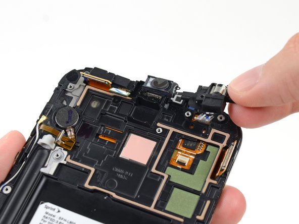
Remove the 3 mm Phillips #00 screw securing the antenna board to the display assembly.
-
-
Dieser Schritt ist noch nicht übersetzt. Hilf mit, ihn zu übersetzen!
-
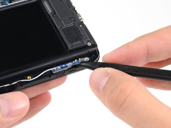
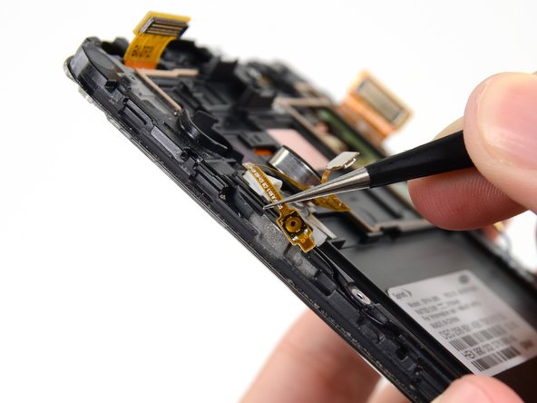
Insert the tip of a spudger under the antenna board to free it from the adhesive holding it to the display assembly.
-
-
Dieser Schritt ist noch nicht übersetzt. Hilf mit, ihn zu übersetzen!
-
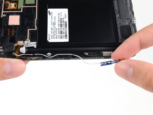
Gently de-route the antenna cable from its channel in the display assembly.
-
-
Dieser Schritt ist noch nicht übersetzt. Hilf mit, ihn zu übersetzen!
-
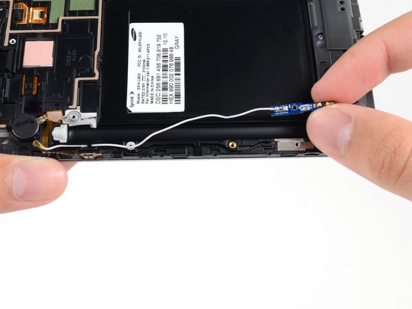
Remove the antenna cable from the display assembly.
-
-
Dieser Schritt ist noch nicht übersetzt. Hilf mit, ihn zu übersetzen!
-
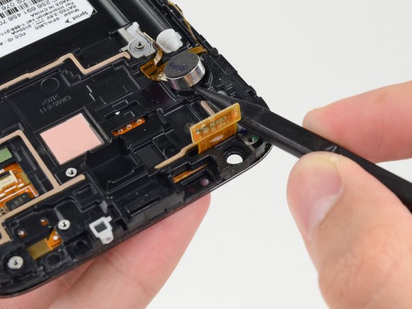
Insert the tip of a spudger under the vibrator to free it from the adhesive holding it to the display assembly.
-
-
Dieser Schritt ist noch nicht übersetzt. Hilf mit, ihn zu übersetzen!
-
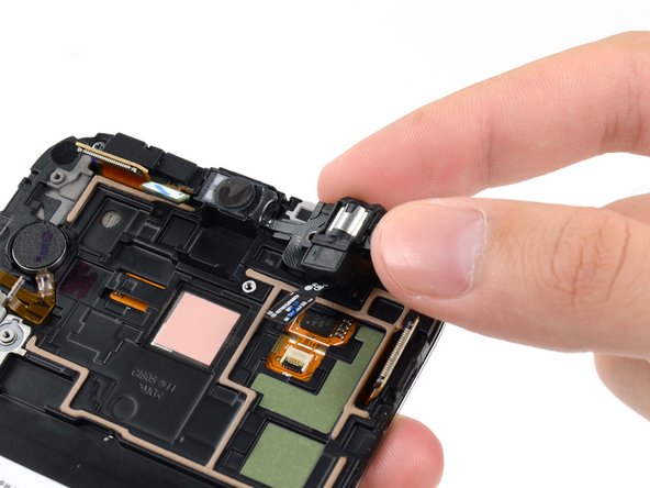
Use tweezers to detach the power button from the adhesive securing it to the display assembly.
-
Remove the vibrator/power button assembly from the display assembly.
-
-
Dieser Schritt ist noch nicht übersetzt. Hilf mit, ihn zu übersetzen!
-
Remove the 3 mm Phillips #00 from the speaker enclosure.
-
-
Dieser Schritt ist noch nicht übersetzt. Hilf mit, ihn zu übersetzen!
-
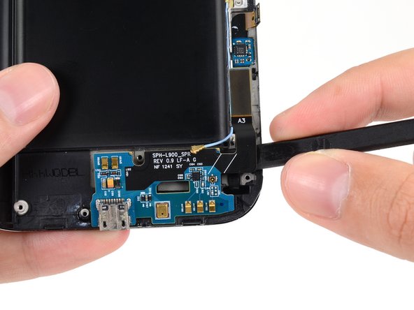
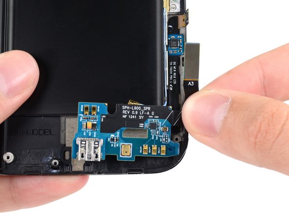
Use the flat end of a spudger to disconnect the antenna cable connector from the USB board.
-
-
Dieser Schritt ist noch nicht übersetzt. Hilf mit, ihn zu übersetzen!
-
Push the flat end of a spudger under the USB board to separate it from the display assembly.
-
Remove the USB board from the display assembly.
-
-
Dieser Schritt ist noch nicht übersetzt. Hilf mit, ihn zu übersetzen!
-
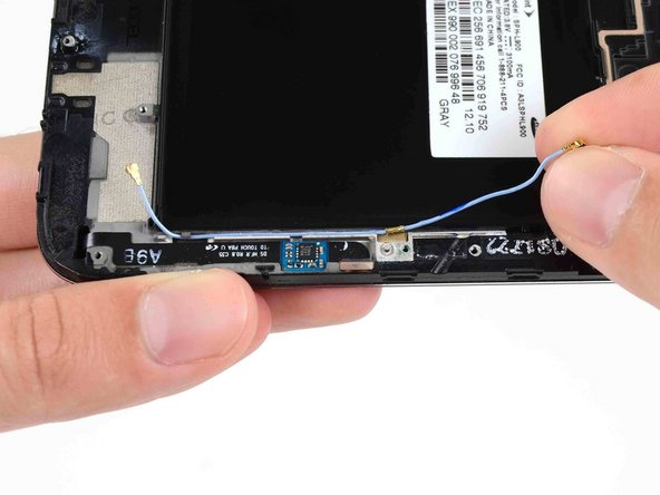
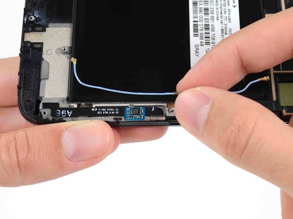
Gently deroute the antenna cable from its notch in the display assembly.
-
Remove the antenna cable.
-


Rückgängig: Ich habe diese Anleitung nicht absolviert.
183 weitere Nutzer:innen haben diese Anleitung absolviert.


12 Kommentare
This guide is awful. Not even the US phone model. mine and most on youtube does not have the antennae on both side, only a antena on one of the sides of the phone.
Also this does not cover how to remove most things that you HAVE to remove when you buy the digitizer+lcd from here... not to mention that it stops in the middle...
there is a video on youtube from https://www.youtube.com/user/LE55ONS that shows how to dismantle the note2 in much more detail than this... and he goes all the way and show how to remove every piece needed.
thx for the video!
note i was repairing looked slightly different. no antenna on the left and powerbutton/vibrator where differnet parts, midframe is hold by 2 additional tabs inside battery compartment. video was a good addition to this guid, and helped alot ;)
Lego -
Thank you for the link to the videos, it helped particularly for the vibrator and power button.
This is the Sprint model, SPH-L900. It's not his fault that your phone is different.
Roger -